iOS Development Workflow

I just had my yearly stress-out about my app expiring. Apple warns you for about a month before the thing expires, and of course I wait until the last minute every time.

Here’s the workflow that worked, first try, once I did *all* the steps.

1) Keychain Access -> login certs -> delete both the “Developer” Cert and the “Distribution” Cert.
2) developer.apple.com -> iOS Provisioning Portal:
2a) Under “Certificates”, *revoke* both the dev and dist certs.
3) Keychain Access (named menu) -> Cert Assistant -> Request new cert from signing authority …-> save to file (saves to desktop)
3a) on the iOS provisioning portal, request a new dev and dist cert, using the desktop file

Now you have certificates. Check this in Keychain Access (and delete the old ones; look at the dates)

4) iOS Provisioning Portal -> Provisioning -> Development Profile create a new one and make sure it’s attached to the latest Dev cert (it’s a checkbox) and choose the correct app (for me, it’s the second “ChooseIt” on the list) and the correct devices (for ad hoc).

5) Do the same thing under the Provisioning -> Distribution Profile.

6) Load XCode -> Organizer and check that the new profiles are in there, or download/import them.

7) In XCode, go to the project window, click the “folder” icon at upper left, choose the topmost “project” icon, and look for the code signing stuff in the center window. Set “Any iOS Version” for “Release” to “Dist” profile and “any iOS Version” for “Debug” to “Dev” profile, everything else to “Do not sign”. Then Clean and Build (might have to stop/restart XCode first). When you get a clean build (I had to go make sure the keychain had only one set of certs and the Organizer had only one set of profiles at this point)…

8) Go back to Organizer -> Archive? (the one with the big app icon and 3 buttons to the right), choose “Share…” -> .ipa -> and name and save the file. Run the .ipa and it will install itself into iTunes.

And that should be that. Now go write yourself a blog entry so you’ll remember how to do it again next year.

oh, wait.

Posted in Computers, Knowledge, Technology | Tagged , , | Leave a comment

CNC – At last!

The CNC machine is functional.

I had been on a bit of a mission lately, to get the machine up and running. Among things that needed to be fixed, replaced, or installed:

– The router bearings were going out, so I upgraded to a Porter Cable 892
– A new router means a new router mount, which I saved some time and effort and bought from BuildYourCNC.com
– The new router needed to be modified to remove the variable speed controller, and have the Super-PID RPM sensor installed
– The Super-PID needed to have its case completed
– The SUper-PID needed a daughterboard to bring connections for Home switches and RPM sensor outside the case
– Hall Effect home switches and their magnets needed to be installed and cables built and run
– Z axis motor cable was faulty and needed replacing
– The cable carrier track was doing more harm than good and needed to be removed

The last time I attempted a cut on the machine, it failed midway through, and I decided that I was going to get the machine fully kitted out before I ruined any more wood.

Tonight, I had just a couple of last things to get done; I installed the Hall Effect switches, and replaced the Z-axis cable.

The Hall Effect switches have been a real pain to get running. First, I fried one while testing it. Then, after I’d built a new one to replace it, I found out that the switches were not wired up in a way that was going to work with the G540 inputs. They were pulling down the G540 input by several volts, even when not triggered, which was causing the G540 to register the switches as permanently tripped. I have enough extra Hall Effect chips to create a new set, but after several iterations trying to fix that problem, I decided to just buy pre-wired Hall Effect switches today, rather than go through the process of rebuilding the switches again.

The new switches also didn’t go right in; a small aside on wiring standards.

The Hall Effect chips are wired +5v,0v,signal, which is both non “standard” (relative to the ubiquitous “servo” connector signal, 5v, 0v), and also allows one to fry the chip if you hook it up backwards, which is exactly how I’d fried mine almost a month ago. I had built my whole system to use “regular servo cables”, but the daughterboard was wired to match the Hall Effect chips, so the wire colors on the servo cable didn’t match the signals going through it. It was all very off-putting, but it was working, and of course I’d just etched a new daughterboard yesterday afternoon, set up for 5v,0v,signal.

So the new pre-wired Hall Effect boards cross the pins around so they can be plugged into a “normal” servo port (like on an Arduino). Grr. So I briefly considered my options; either wire up a jumper cable, or re-create the daughterboard, or both. I decided to wire up some jumpers. And actually, now that I’ve done that, the wiring makes a lot more sense again; I just hook the stuff up so that the wires go where they’re supposed to, and all the colors match up with the pins they’re supposed to, and there’s no way to hook it up backwards (because I have keyed servo leads). Best part of all, the whole thing worked the first time I tested the jumpers. w00t!

I got the X and Y switches installed, and because I had a little dab of Sugru left over (I love Sugru by the way — I have about 4 layers of the stuff on each spot where the switches go 😀 ), I mounted up the Z-axis switch, too. Then I decided “what the heck”, and wired up another jumper and a looong Z-axis servo cable, and just like that, I had home switches on all 3 axes!

Hardly believing it would work, I fired up Mach3, and homed each axis. I had to flip a couple of “Home Neg” settings, but other than that, they all worked great. Seeing the little LEDs come on as the axes homed in was very satisfying.

I can now “Ref All Home”, and it drives Z to the top of its run (backs off a little when it hits home), then Y to the end of its run (backs off), and then X to the end of its run (backs off), and zeroes the DROs! So Cool!

With a repeatable home setting, I put in soft limits for all 3 axes, and tested the limit on the only axis I can do safely, Y. Ran it out to 48″ and it slowed to a stop right on cue.

With the axes homed, I decided to try out the new router under speed control. It worked flawlessly. Spindle on/off, S10000, S20000, S30000 all did their jobs. The RPMs and the requested speed are not quite right, but I’m pretty sure that’s a function of the pulley settings.

At this point, I just need to put in a collet and endmill, and load up some G-code!

And when the silly machine loses its place in the middle of a job, I can just re-home it, and keep going.

It’s been a long tough road, but I can finally say I’m ready to cut on the big CNC.

Posted in Electronics, Knowledge, Making, Technology, Woodworking | Tagged , , , | Leave a comment

PCB Fabrication – Getting the hang of it

With my first PCB under my belt, I was ready to etch a board for something I really need. I took the lessons learned last week, and was able to produce a really nice result this time.

I left the etch resist on, because it actually acts as solder flux.

I left the etch resist on, because it actually acts as solder flux.

This is a daughterboard for the Super-PID on my CNC machine. It breaks out the power and RPM sensor for the Super-PID, and also exposes the inputs from the LPT port breakout box so that I can attach home switches to the X, Y, and Z axes.

I had already built this circuit in perfboard, but the home switches weren’t working properly, and I realized that I needed to add diodes on the parallel-wired Hall Effect sensors. I breadboarded a test sensor, confirmed that the diode made it work, and went about capturing the schematic in Eagle.

The original was done on perfboard. Note this one lacks diodes.

The original was done on perfboard. Note this one lacks diodes.

I had to match the original circuit form factor, because of the way it’s installed; half of the circuit lies inside the Super-PID case, and half outside. So I measured the distance between the mounting holes carefully.

I also decided to add a ground plane; etching away tiny little traces makes the etching go a lot faster.

I used a Sharpie to mask off all the parts of the board that didn’t have circuit on them. These two steps made the difference between “made it!” and “whoops, gotta head to the store again” today, because I realized as I was setting up that I am now officially out of vinegar. I had just enough to do one batch of etchant, so I had to make it work.

I used Sharpie to mask off as much as I could that wasn't part of the circuit.

I used Sharpie to mask off as much as I could that wasn’t part of the circuit.

I love how clean the board looks with the ground plane.

Looks pretty sweet from the top side.

Looks pretty sweet from the top side.

I decided to leave the etch resist on, as I read somewhere that etch resist is actually intended for use as solder flux. I wonder if it will protect the traces long-term, too. The little green pads did hold solder pretty well.

Because I wasn’t pushing the etchant so hard, I got a lot of fine detail in this build; next time I might make the font a little darker, but even the really little stuff is readable.

In all, this board went together a lot easier than the last one, and I’m really pleased with the results. All the traces look really clean, and I didn’t have to do any editing with the tip of a utility knife this time.

So the actual workflow was about the same; I added in a ground plane, I cut the board to the size of the circuit, and I did some careful masking (note to self: next time, mask with tape instead of Sharpie). I made myself new developer, and it worked just fine this time (I used warm water). So I now have a jar of usable developer for next time.

I attempted to switch to HCl / Cupric Chloride etching, but the “30% Hydrochloric Acid” junk I got at the pool supply store was useless as an etchant — it was dyed orange, and spent a lot of time foaming and attacking the etch resist instead of the copper. Yuck. I’ll have to try HCl again sometime, but I have to find a brand that works. Maybe a hardware store instead of a pool supply place.

I also picked up some real cheap “Injectorall” boards from Digikey. I was Not Impressed. The boards did not come with a peel-away protector for the photoresist, just a black plastic bag with a white piece of paper over the resist. Also, the stuff apparently really does want UV light, because 20min under a 100W lamp did not make much of an impression. It also took forever to develop, and when it did, there were huge holes in the resist where I could see pink copper underneath. In short, those boards are destined for being stripped of resist, and used for toner transfer or art projects.

In contrast, I used an MG Chemicals board last time, and a Datak board this time, and they both worked fine. Nice green resist, took the artwork well, etched up fine even with the weak vinegar/H2O2 solution.

I need to figure out transparency film. There are apparently 5 or 6 types with varying price points. But the guy at Kinko’s really hasn’t gotten a nice, dark print for me yet, even when I requested he make it as dark as possible today. So I think that I’m going to have to figure out how to produce dark lines on transparency on my own. I mean, the artwork is coming out “OK” on the boards, but it seems like it should be.. darker. Much, much darker.

I finally installed a light on my drill press, so I can see what I’m doing with the little teeny through holes. I drilled the whole board without breaking a drill bit. w00t!

It was very satisfying to see the limit switch light up on the PC when the Hall Effect sensor tripped.

Posted in Electronics, Knowledge, Making, Science | Tagged , , , | Leave a comment

PCB Fabrication – been there, done that.

Well, I did it.

My first PCB.

My first PCB.

I decided to tackle something simple for my first attempt at etching a circuit board. I wanted something with a low parts count, and that was easy to test. I decided on a voltage level shifter circuit, as it only requires a MOSFET and 2 resistors per channel, and 4 channels is generally sufficient for most digital protocols.

I spent a day learning Eagle CAD, in which I created, destroyed, and re-created the circuit about 5 times. I ended up with a very clean-looking schematic, and two separate boards (both hand-routed); one for SMT parts, and one for through-hole. Both boards are really tiny; they easily fit on a breadboard.

Since the boards are so small, I decided to etch several, in case the etching went weird on me. So the PDF had 6 copies of the PTH board, and 9 copies of the SMT one.

I don’t consider myself an Eagle expert at this point, but I certainly got to learn how to find and place parts, name my nets, and route traces on both the top and bottom layers. I really should write up the Eagle work in another post. Note to self.

Anyway, at the end of the day, I had a PDF on a USB stick. I took these to Kinko’s, and printed the PDF for one dime on the self-service printer. Then I let the Kinko’s guy talk me into letting him do the copy onto a transparency, for which he charged me 82 cents (oh, the humanity!) *and* I forgot to remind him to use the highest density on the copy, so it came out a little dim. Live and learn.

I got the transparency home, chopped it up, and purloined a picture frame.

Transparency was created at Kinko's. Cost me nearly a whole dollar.

Transparency was created at Kinko’s. Cost me nearly a whole dollar.

I did my little darkroom thing, got the board taped down, and put it in a well-lit room for 20 minutes.

Meanwhile, I ate a frozen entree so I could use the empty plastic tray for my developer. 1 part developer (NaOH), 10 parts water (used cold from the tap — I bet it would have gone faster if it was a little warmer), and when the timer went off, the board went right in.

Board in developer. Magic has not happened, yet.

Board in developer. Magic has not happened, yet.

I was led to believe that this part of the process would take about 1 minute. When a minute had gone by and nothing had happened yet, I was fully convinced that I had messed up somehow. I kept developing, and within a few minutes (probably less than 5, but I was pretty stressed out at this point), this happened:

This part was pretty magical. It really felt like I was "making" something, now.

This part was pretty magical. It really felt like I was “making” something, now.

This part was very exciting. I was not sure when exactly the developing process was done, nor how much I could mess with the board during this time, so I don’t think that I got as much of the photoresist off as I should have. This probably caused a problem during etching — but at the moment, I was worried that the developer was going to eat my traces, so…

Board out of the developer. I probably should have spent a little more time getting all that green off..

Board out of the developer. I probably should have spent a little more time getting all that green off..

I washed out the plastic bin (saved the developer in a glass jar for next time), added 1 part vinegar (acetic acid) to one part hydrogen peroxide (H2O2), a touch of salt, and put in the board.

I was etching a 1oz copper-clad board, and I hadn’t put down a ground plane (I tried! really I did!), so I knew there was a lot of copper to remove. But etching. Took. Forever. I kept adding salt, the etch was just going very slowly, I tried foam brushing a lot, I tried sloshing the board around. Eventually, I realized that the etchant was looking shot, so I dumped it and poured in a whole new batch of etchant, lather rinse repeat, made a little more progress, but still needed a third batch of etchant to finish the job. The last batch, I put in a lot less salt. I think that helped. But by the time I finished, some of the photoresist was looking pretty thin, in the middle of the board.

It took over an hour and a half (I was led to expect ~20 minutes) to etch the 3″x5″ board.

It took 3 refills of etchant, but here's the board down to mostly bare fiberglass.

It took 3 refills of etchant, but here’s the board down to mostly bare fiberglass.

A quick swipe with nail polish remover, and I headed out to the shop to separate the individual boards, and drill the holes.

Separating the boards was done with a hacksaw. I’ll probably use the tablesaw next time, but I was pretty fried at this point and just wanted it done. The boards are wonderfully non-rectangular, too. 🙂

I was pretty fried after etching took nearly 2 hours. I cut the boards apart with a hacksaw.

I was pretty fried after etching took nearly 2 hours. I cut the boards apart with a hacksaw.

I started drilling on the big drill press, but I was having lighting problems (I need to install the light on the drill press. Another note to self. So I moved to the Dremel. I’d forgotten how much I hate Dremel tools. They just stink. The motor is weak, the collet won’t hold bits properly, there’s a ton of runout… yuck.

I broke 3 bits trying to drill out 2 of the PTH boards. I didn’t even bother with the SMT ones, because it turns out you can’t buy SMT parts locally on a Sunday in Seattle. I mean, really. What is the world coming to?
I got the holes drilled (only a few mistakes there), then headed back inside because I realized I was going to need the schematic in front of me while I was soldering.

Just starting to populate the board. Pretty cool! Note I had to mirror the board on the screen so I could figure out what was what.

Just starting to populate the board. Pretty cool! Note I had to mirror the board on the screen so I could figure out what was what.

It took a second to figure out how to install all the parts; I had to mirror the layout on the Mac screen so that I could get the holes all lined up.

I was also unable to find SIP resistor packages, so I had to invent my own; I’m absolutely certain I’m not the first person to think of this, but essentially, the SIP packages have a single power pin (tie HIGH or LOW) and a bunch of resistors, so I just twisted together one lead from all 4 resistors, and used that to tie one leg of each to the positive rail. Clever trick, doesn’t even look half bad, but I’d rather just have a SIP package. 🙂

Fully populated! Time to test.

Fully populated! Time to test.

I spent some time ohming out the whole circuit. I found 2 shorts caused by imperfect etching. The rest of the board seemed solid, and I was getting the readings I expected, so I decided to bit the bullet and test the thing.

I set up the breadboard as follows:
– ground rails tied together.
– far side is the HIGH side, power rail driven by a FTDI cable attached to the Mac (running on battery)
– near side is the LOW side, power rail driven by an Arduino plugged into a USB charger wall outlet.
– I set up an LED on the HIGH side with a 1K pullup to 5v (from the FTDI) and ground pin going to channel 4 on the HIGH side of the new board
– I set up an LED on the LOW side with a 1K pullup to 3.3v (from the 3.3v pin on the Arduino), and group pin going to channel 3 on the LOW side of the board.
– I put in a jumper wire on the LOW side on channel 4 (other end not plugged in)
– I put in a jumper wire on the HIGH side on channel 3 (other end not plugged in)

The idea is that the HIGH LED will only light if its ground pin goes to GND, and the only way that’s going to happen is if the LOW channel 4 pin goes to GND.

Ditto for the LOW LED and the HIGH channel 3 pin.

The two rails on the breadboard are at different voltage levels! This side is at 3.3v...

The two rails on the breadboard are at different voltage levels! This side is at 3.3v…

...and this side is at 5v!

…and this side is at 5v!

It worked! The LEDs only lit when the opposite side channel (which are not connected normally) went LOW.

You can see me checking the voltage across the 2 resistors. This is after the voltage drop of the LEDs, of course. One is at 1.7v (on the 3.3v side), and the other is at 3.1v (on the 5v side). W00t!

So now I have a simple-but-useful circuit. Actually, with a little soldering, I have about a dozen of them. 🙂 Anybody need a level shifter kit?

More important, though, I designed, CAD’d, exposed, etched, and drilled the circuit, and it worked on the first try! I feel like a whole new world has opened up to me.

That was Immensely Satisfying.

Posted in Electronics, Knowledge, Making, Science | Tagged , , | 10 Comments

Thinking about PCB creation

So far, I’ve been able to successfully avoid making my own printed circuit boards (PCBs) for all the electronics projects I’ve done.

Between Protoboards (letting someone else do the etching), perfboard (which I hate, but end up using), and “deadbug” construction, I have been able to bob and weave my way out of learning this valuable skill.

Well, it’s a set of skills, really, isn’t it?

To create a PCB, you have to execute the following steps:
1) design the circuit
2) lay out the circuit onto a board
3) create the copper traces on the board
4) drill the through holes
5) solder the board together

Steps 1 and 2 require a deeper understanding of Eagle, which I’ve not really bothered to do, because I haven’t been serious about creating boards.

Step 3 (and possibly 4) are what I see as The Giant Leap. You can lay down traces on a board in essentially one of 2 ways. You can either chemically etch away some of the copper, or you can mechanically carve away some of the copper. There are other, less-interesting-to-me, ways of doing it (drawing the traces with a silver pen, carving out traces by hand, etc), but I’m going to ignore those.

Let me start with the mechanical method first.

One of the reasons that I built a CNC machine was to use it to make PCBs. The idea of building the circuit in Eagle, then sending the graphics to the CNC, seems like a perfect use for the tool. You can also drill the through holes at the same time as cutting the traces! Having said that, I’ve not done it yet. There are several reasons why, but let’s start with just two. First, I haven’t really figured out how to use small drill bits with the CNC yet; speed control and collet size are both contributing factors. At the moment, I can only use 1/4″ endmills. It seems like the precision endmills are mostly 1/8″ shank. Second, I have doubts about the accuracy of my CNC; it seems like every wood project I build ends up getting cut 2 or 3 times, because the machine freaks out in the middle of the cut; or I end up having to do a lot of sanding of the workpiece at the end, because it has lots of rough edges or scalloping or similar.

Both of these problems have made me shy away from doing CNC circuit boards. I could probably overcome the problems, but I haven’t bothered, yet.

This takes us to the chemical method. The idea, here, is that you take a copper board, lay down some kind of mask to protect the copper you want to keep, then use some kind of chemical soup to etch away all the copper that’s not covered by the mask. Once you’re done, you wash off the mask material, and you’ve got a board that’s ready to be drilled and soldered.

Let me stop at this moment to say that, because of my very odd educational career, I made it all the way through high school and college without taking a single chemistry class.

So, let’s break this down into “creating the mask”, and “etching the board”.

There are essentially 2 ways to create the mask. You can either deposit some kind of material onto the copper (like the toner transfer or Sharpie methods), or you can use a photosensitive copper board, and “develop” the traces onto the board. The toner transfer method always seemed kind of grungy to me; there was a lot of “you need a laser printer” and “print onto shiny magazine paper” and “you have to rinse off the board in water to get the stuck paper off” sorts of instructions. I’m sure that it’s a fine method of doing things, but it bummed me out somehow. I admit that I had some problems with the photo-mask method, too — the etching process already includes a lot of chemical mumbo jumbo that I’m not necessarily comfortable with, and now I need to add another layer of that into this process? Yikes.

Having said all that, I at least understand what the concept of this part of the process is; take a fully-coppered board, and put the circuit traces on it. Accurately.

Now we get into the actual etching.

So the idea, here, is that you have a bunch of copper on the board, and you need some of it to go away. So you need to use some kind of acid solution to remove the unwanted copper. There are a multitude of acids that will do the trick; this is where various religious arguments start to take place.

The time-honored method, used worldwide, probably by professional board-making houses and everything, is using Ferric Chloride. I don’t know what the stuff is; I stop reading as soon as they talk about how toxic the stuff is, and how much *more* toxic it gets when you add copper to it (the stuff that etches off the board goes into the etchant). There are a lot of warnings about “don’t let this spill on your clothes” and “definitely don’t breathe this stuff” and “use the real thick kitchen gloves for this” … no thanks. I have little kids in the house. The last thing I need is one more hugely dangerous chemical lying around.

The next-most-widely-suggested method (from my informal survey of reading and dismissing the idea of doing this over the years) is using HCl (hydrochloric acid or muriatic acid). Now, this is the stuff that’s in your stomach, so it’s not necessarily the most evil stuff ever, but again, the posts talk about “you use it to maintain the pH in your swimming pool”. I guess if I had a pool, I’d have the stuff, and I wouldn’t think twice about it. But I’m not bringing extra stomach acid into the house if I can help it.

Then I saw this post by Quinn Dunki (who is a LadyAda-caliber electronics demigoddess in her own right) about etching PCBs using an etchant that is, essentially, safe to drink. I’m not drinking it, especially not after it’s got copper in it, but the stuff in it (vinegar and Hydrogen Peroxide and table salt) really is pretty tame. Seeing the resulting boards and knowing that the input chemicals are safer, really made me think this one over. There’s still the question of what to do with the used etchant (can it be reused? can it de dumped down the drain? send it to a landfill?), but I’ve been pretty convinced by the various debates I’ve heard, that this stuff is actually kind of good for your septic system (in small quantities) — hardware stores sell copper sulphate as a root killer for use in the garden.

OK, OK, I’m convinced.

So, what do I need to have on-hand in order to make boards? I’m going to parse through the post and collect a materials list.

for Safety:
– nitrile gloves
– eye protection

For the mask:
– acetate sheet (Kinko’s?)
photo-sensitive PCB
– blue painter’s tape
– old picture frame
– daylight-spectrum CFL bulb (or regular desk lamp)

To develop:
– Tupperware tub (sized to fit the board)
positive developer

To etch:
– something to do for 20 minutes
– Tupperware
– vinegar
– hydrogen peroxide
– salt
– foam brush
– acetone (nail polish remover)

To drill:
– tiny, tiny drill bits (#69, #67)
– lighted, head-mounted magnifier

Now, my understanding is that this is all for single-sided boards. You can apparently do double-sided boards (or a smaller 2-sided board can be gotten locally) by developing one side, then sticking in some registration pins, and working the other side. That sounds complicated.

A few personal reminders:
– If you’re doing through-hole components, put all your traces on the “bottom” layer. If you’re doing SMT components, put all your traces on the “top” layer
– The “top” layer needs to be *mirrored* before printing! The “bottom” layer must *not* be mirrored.
– Don’t add too much salt to the etchant.
– Try to keep everything at room temperature.
– Possibly fresh ingredients work better than stale ones.
– Can etchant be regenerated/reused?
– max density on the transparency
– only 2 layers of transparency
– make sure all the photoresist is gone

Posted in Electronics, Making | Tagged , | Leave a comment

NAS is the new Plex

In my continuing battle against the $70/mo “cable” bill (I have satellite TV, but same guts), I have been pushing both hardware and software at the problem. So far, I’ve tried:

Here’s a short history of recent events.
In November, the Tivo started acting up, so I turned it off, and added an IP TV Tuner (HD HomeRun) to pull down live TV off the air.

To perform the DVR (scheduling, recording) function, I put EyeTV software on the Mac Mini (an older, 2GHz CPU with 2GB of RAM).

To decrease the “hop count” of how far all this data has to travel over the network, I moved the external USB 2.0 hard drive (2TB) to the Mac Mini.

Because the hard drive is now on the Mini, I moved the Plex Media Server (which acts as a file server for movies and recorded TV shows) to the Mini also.

The Mini was also acting as the main Plex client (attached to the TV).

So, this poor little box is doing a lot of work:
– writing up to 2 HD video streams at the same time
– reading possibly many (but generally no more than 1 or 2) HD video streams
– rendering at least one HD video stream to the TV

The Mini was … not doing well… with all this.

So, I tried offloading work from the Mini. I started with moving the Plex Client to a Roku XS (which has a very nice and easy interface).

I became concerned that the weak point (or “one of the weak points”) in the system is the USB 2.0 link between the Mini and the Media drive.

So, I decided to pick up a NAS (Network Attached Storage) device. It’s essentially a hard drive with a ethernet cable coming out of it. The hope is that the network will be faster (or more reliable) than the USB 2.0 connection for streaming all those files in and out. Also, hopefully client boxes like the Roku can connect directly to the NAS, instead of going to the Mini first.

After much gnashing of teeth and tearing of hair, I landed on the QNAP TS-412 NAS. It has 4 drive bays, and dual ethernet ports. The dual ports sold me, as I can probably find a way to segment my network so that client boxes get their own private connection to the box, and the EyeTV server can have a different one. I also picked up a pair of 3TB Seagate drives.

All of this gear showed up on my doorstep last night.

The NAS box itself looks a bit utilitarian, but setup was a breeze. I really liked all the little extras: it came with 2 bags of screws for mounting drives, as well as a pair of Ethernet cables. I mounted the drives, plugged it in, and did the initial setup and firmware upgrade (downloaded 3.8.1 off of the QNAP website). It turns out that the NAS will do a whole bunch of things that I may or may not use it for; it can be a Surveillance camera hub, run a web server (including MySQL DB), or even be a printer spool for up to 3 USB printers!

There’s a “one touch copy” USB port on the front. I hooked up the 2TB Media drive, twiddled the settings a bit, and started copying files a bit before midnight… this will take awhile.

While files were copying over, I poked around on the box to see if there were any other settings I could try out. And I decided to try an experimental build of Plex Media Server (PMS) that someone had cross-compiled for QNAP.

In short, it worked perfectly. Plex went right in as a new “app” on the NAS, and it started scraping my Movies folder and downloaded metadata and cover art!

I tested the new server from the Plex client on my laptop, and it spun right up.

So now the NAS is becoming the new Plex Media Server for my network! This means that the Mac Mini gets 2 more things offloaded (no USB drive and no PMS), and it’s down to just dealing with EyeTV scheduling and recording (and maybe some Live TV if that’s how we end up doing that).

I will still have to do more testing to make sure that the Mac Mini can handle its ever-lightening load. If it can’t handle EyeTV, I might have to offload that to a different machine (maybe the iMac, or my laptop… or maybe even the NAS box).

In case all else really fails, I might even be able to press the Raspberry Pi into service.

With fits and starts, I limp towards a solution for getting rid of DirecTV forever.

Posted in Computers, Knowledge, Technology | Tagged , , , | 2 Comments

CNC – going in a new route

My new Porter Cable 892 router showed up tonight. First thing I did of course was to remove the handles so I can start looking at getting it mounted to the CNC.

I’m going to have to do some cutting in order to make a mount for the thing, and that means getting the CNC back on track, and getting the DeWalt router to give me “just one more cut”.

But I’m confident that the new router will keep me going for quite some time.

Once it’s installed.

Posted in Making, Woodworking | Tagged , | Leave a comment

Super PID first light

All’s well that ends well.

I had a long day out in the shop today, and it was filled with a lot of trials.

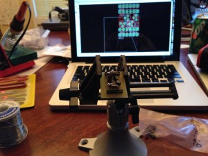
First, I spent a little time working on the foot for the NJP mount. I’m kind of working a lot of projects at once, here, but I was pretty close to being done, so I wanted to get that complete. Things went together, and it looks awesome. More about that on the other blog.

Then, I needed to put a servo cable end on the RPM sensor for the Super-PID. That took a couple of tries, but I got it done. While the soldering iron was hot, I decided to also solder some male header pins onto the Hall Effect sensors. That went ok, too, although there’s not a lot of pin sticking out to solder to, and the smell of burning Sugru is not awesome.

I wanted to test the Hall Effect sensors one more time to make sure I hadn’t killed them with all the soldering. In the process of testing, however, I must have cross-wired something, because I blew one of the sensors. Argh. I will have to go back through my notes again, and construct a new one. I carefully tested the other 2 sensors and they’re working fine. I may run the machine with just X and Y home switches for a bit. I was very disappointed in myself that I messed that up.

However, it was probably for the best; as a result of blowing up the sensor, I decided to carefully test the wiring of the Super-PID case. It’s a lot of new wiring, and I didn’t want to blow anything else up.

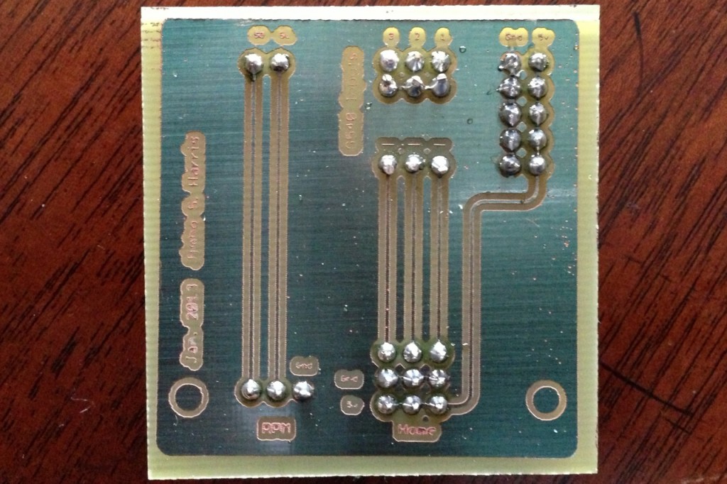
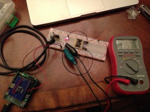
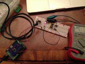
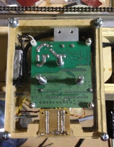
First, I put 5v and ground into the wires on the DB-9 port on the side of the case. I confirmed, piece by piece, that things were working when powered like that; first with all plugs out, I tested the perfboard to make sure that I was getting 5v and ground where I thought I should. Then I plugged in the Super-PID and tested it again. It powered up just fine. Then I tested the new RPM sensor wire, and that worked, too (I could turn the endmill by hand and see it flash up and down past the sensor). I even tested the mains voltage to make sure that the board could see the 110vac.

At this point, I was getting over my fears about the new circuit, and I was just about to plug the thing into the computer and boot up, when I decided that I should test the cable coming from the computer first. I started getting some weird readings, and decided to test continuity on the CAT5/DB-9s. I discovered a bad CAT5 cable that way. Whew!

Then I started probing the cable for 5v and ground, to make sure I was wired up the way that I thought I should be, and I noticed something was decidedly odd about the readings I was getting. I knew the cable was OK (and the ends were straight through), so couldn’t figure out what was going on without tearing down the computer side of things.

So, I dismounted the PC, got it up on the table, and started ohming out the connections between the G540 and the DB-9 connector. I finally got to the bottom of what I had been attempting to do with the cabling, and I found that I’d somehow flipped 4 of the pins on the DB-9 connector on the Super-PID.

?!?

I double-checked everything carefully, and indeed, I had wired it 4-3-2-1 instead of 1-2-3-4 (with 2 of those pins being +5v and Ground!). I am *so* glad I took the time to check the connections before I hooked it up!

Once I found the problem, I looked for its source, and found it immediately — I had written up the diagram incorrectly in my notebook. *facepalm* The pins were numbered correctly (although poorly annotated — I didn’t realize, 4 months later, that I’d written down “G540 pin number” instead of “DB-9 pin number”), but they were *labeled* incorrectly, and of course I followed the labels as I wired up the new connector.

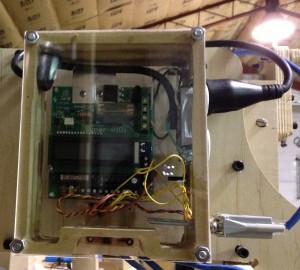
I corrected the error in the notebook (and added some extra annotations), then de-soldered and re-soldered the DB-9 port on the Super-PID. I spent a little extra time going through and making sure I completely understood all the connections, re-tested all the voltages, and, breath held, I plugged into the computer and powered up all the way from the G540 through to the Super-PID.

It worked!

Discovering, Diagnosing, and Repairing an error I’d made 4 months ago took the better part of the afternoon. By this point, my brain was pretty fried.

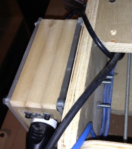
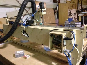
During the middle of all the testing, I decided to re-work the cable runs going to the router. I haven’t been happy with the cable channel I bought (it actually caused a machine failure last time I was doing a cut), so I removed that. In addition, I had a couple of new cables to run (there are now 5 of a future 6 wires plus the vacuum hose, that need to move with the Z table), so I removed the channel, and worked up a new solution. I’m now running everything directly to the vacuum hose, which I think will keep cables from fouling. I’ll probably use some of the same split-channel that I used for the NJP wiring harness, to keep everything nice and tidy. For now, it’s still being held in place by Velcro.I really like the new cable run, though — it looks pretty nice, and I think that it’ll work without binding up.

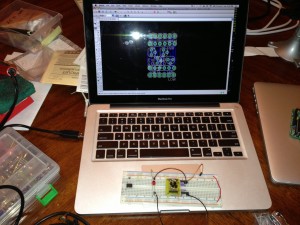
I decided to fire up the computer and do a test all the way through Mach3. I got the computer re-mounted, got all the cables plugged in, and booted up. As if I hadn’t had enough trauma for the day, the mouse needed a new battery. Can you feel my eyes rolling?

I got Mach3 up, put in all the configuration parameters from the notes I’d written in the notebook (deciphering took a few passes), and told Mach3 to turn on the spindle.

Nothing happened.

To say that I was a little disappointed at this point would be a vast understatement. Was I facing a problem in hardware? firmware? software? cabling? configuration?

I’d just been fighting this thing all day, and working to get to this moment for several working days over the course of a year. Was this *ever* going to work?

I was so fried at this point that I just needed some time away. I shut everything down, and went to dinner. A couple of hours later, I was seeing if the ‘net could help me to diagnose the problem, when I had a flash of inspiration. I headed out to the shop, changed 2 parameters, and voila! the router started spinning at Mach3’s command, and the tachometer in Mach3 started reading back the same RPM that the router was reading. Cool!

The configuration parameters I changed? I had put the Super-PID onto the G540’s Output 2 (it has 2 outputs; don’t know why I didn’t do output 1, don’t ask), but since most people use Output 1 for this, the configuration I’d copied down for “which LPT pin to toggle for the RUN pin on the Super-PID” was set to the wrong pin. Fixing that, the router fired right up. Also, the TACH input was set to the wrong LPT port. Tweak that, and the tachometer started working. There’s a whole lot of “pin X” translates to “pin Y” in this build — from LPT to G540 to DB-9 (there are 4 of these that come in 2 mirror-image pairs) to CAT5 to Super-PID… I’d captured all the data, but I’d just missed that last translation (output 1 vs output 2).

I was tickled that I’d carefully diagnosed all the hardware errors before booting the thing up, and that the only problem was in configuration.

Three more errors manifested at this point, but my confidence is high that I’ll get them solved quickly.

First, for some reason the router is only running at 5,000rpm. That’s the “minimum” value, so this means that the Super-PID is not getting a voltage difference across the “potentiometer” pins from the G540. It’ll take some looking at, but I’m not going to stress about it for now.

Second, the Y-axis motor, which has plagued me for a long time, is not working right. Again. It was doing the stuttering thing that turned out to be a cold solder joint last time. I assume this is due to re-cabling the gantry. I’ll get it worked out, but it has nothing to do with the Super-PID, so it’s just another bug to crush, not something that I just broke.

Finally, the bearings in the router are sounding really terrible. Running at 5k rpm, the router would normally be almost silent, but it was screeching and caterwauling away. So, when I went back inside, I did a little final research, and decided to buy a Porter Cable 892 router. I have a couple of spare routers around, but none of them will fit the CNC without modification. The BuildYourCNC folks build their machines around PC892 routers, so rather than continuing to swim against the current, I decided to just do it. The router will be here in a few days, and of course I need to cut a new mount for it before I can use it.

Installing a new router mount will give me some time to redo the Z-table. I really need to replace the 3/8″ socket-head bolts with pan-head ones, and get everything tightened up and ready to roll.

The Super-PID is installed. It is being controlled by Mach3. For now, I am declaring victory.

TODO:
– new Hall Effect sensor
– 3 servo cables for the home switches
– new router mount
– modify the new router for Super-PID control
– buy new Y-axis rails
– tighten up the Z-table
– Super-PID RPM control
– Y-axis motor connector

Posted in Electronics, Making, Woodworking | Tagged , , , , | Leave a comment

Super-PID installed

I finally got the Super-PID installed today.

20130112_CNC_SuperPID_detail

A good friend of mine brought over some 1/4″ acrylic so I could finish off the Super-PID case. I spent the day figuring out how to make it work.

I cut off a chunk with the tablesaw, that worked pretty good. I also cut it to length with the table saw.

I started trying to drill the mounting holes, and found that drilling acrylic is a bit more difficult than drilling wood. I cracked the plastic on fully half of the corner mounting holes, but I decided to press on anyway.

I carefully dotted the plastic where I wanted the Super-PID and I/O board to mount, and then went on a hunt for hardware that would work to mount it all up. I found that the feet on the Super-PID were self-tapping and would work with 6-32 hardware, and I had some really short ones lying around (~1/2″ — nice). The I/O board really wanted 4-40 hardware, and that took a lot of work to find. Apparently I don’t do enough computer hardware work, as I am pretty sure that 4-40 is pretty common on old-school interface ports (DB-9 etc). Anyway, I finally found enough hardware to get it all mounted up, and was able to drill holes right where I wanted them, and as if by magic, everything mounted up perfectly the first time! No extra holes. Amazing.

20130112_CNC_SuperPID_bolted

I needed to figure out how to mount the unit to the CNC, and after starting to think down the path of a keyholed system, I finally landed on simply bolting the thing on. I found some places where I could drill holes, drilled 3 of them (first in the plastic, then through the gantry).

20130112_CNC_SuperPID_gantry

With about 10 minutes of assembly, the Super-PID is mounted to the CNC!

20130112_CNC_SuperPID

All that’s left is putting a servo connector on the RPM sensor, and I’m ready to test.

It feels really, really good to have the Super-PID installed. I feel like I’m ready to start cutting again really soon.

Ironically, of course, once I get the Super-PID working, I’ll be able to CNC acrylic…

Posted in Making, Woodworking | Tagged , , , , | Leave a comment

Bathroom scale v1.2

I’ve been using the XBee-enabled bathroom scale for almost a year now, and it works a treat. Every morning, I hop on, the weight goes to the computer, and the computer dumps the weight reading into a logfile. The server side is written in Python (which treats the XBee like a regular old serial port, which is nice), and it can even attempt to determine who’s standing on the scale (based on how close the reading is to the known weight of each user).

It’s been a good tool, as I said, but there are two glaring user interface problems that leave it in a state where I’m willing to deal with it, but it’s not really ready for prime time.

First, I never really solved the power problem — I can’t get the Arduino and XBee to sleep deeply enough using software to keep the battery running even overnight. I played around with sleep mode and interrupts but just couldn’t get the power consumption right. Oh well. So I unplug the battery after every use. I eventually found a hardware circuit involving the Arduino keeping a transistor (and, thus, its own power supply) alive until it’s ready to go down, then shutting off the transistor, which cuts power to the circuit completely. I haven’t tested this, but it sounds like a winner. Someday, I’ll be irritated enough to get that done. 🙂

Second, I discovered that XBee’s range is not like WiFi’s range; those little chip antennas really have to be in line of sight of each other, and frankly sometimes 10′ is too far for the signal to go through, if the antennas happen to be pointed in odd directions, and if you’re unlucky. This is not a catastrophic problem, except that unless you can see both XBees at the same time (and my bathroom is not set up for that), you can weigh yourself, head back to the computer, and find that the weight didn’t go through. Grumble. Not what you’re looking for first thing in the morning.

While reading Igoe’s wonderful book Making Things Talk, I had an epiphany in the section about handshaking. Essentially, you make each side “acknowledge” a transmission from the other, and you wait for that “ack” before you move on.

I decided that this was the way to prevent the morning “oops it didn’t get received” problem, but it took months for me to get back around to fixing it.

I’ve been working my EE mojo for the past couple of weeks, and I finally decided that today was the day to fix this.

I added a line to Python side, to send a linefeed upon a successful weight reading receipt.

On the Arduino side, I needed to slip the code into the working sketch without breaking it, and I needed to be able to alert the user to either a success or failure condition. I decided to use LED blinks to alert the user, as the person will be standing on the scale, staring at the LEDs already, and since I was already using the decimal point LEDs to indicate a stable weight reading, I decided to flash those LEDs (2 slow flashes for success, 5 fast flashes for failure) to indicate the status.

I also needed to recall how to program the Arduino. Turns out I left it in a state where I could unplug the XBee, plug in an FTDI cable (careful where GND goes!), and program it directly.

All of the code went together perfectly, and the scale software is much more user-friendly. Nice!

Posted in Electronics, Making | Tagged , | Leave a comment