
With my first PCB under my belt, I was ready to etch a board for something I really need. I took the lessons learned last week, and was able to produce a really nice result this time.
I left the etch resist on, because it actually acts as solder flux.
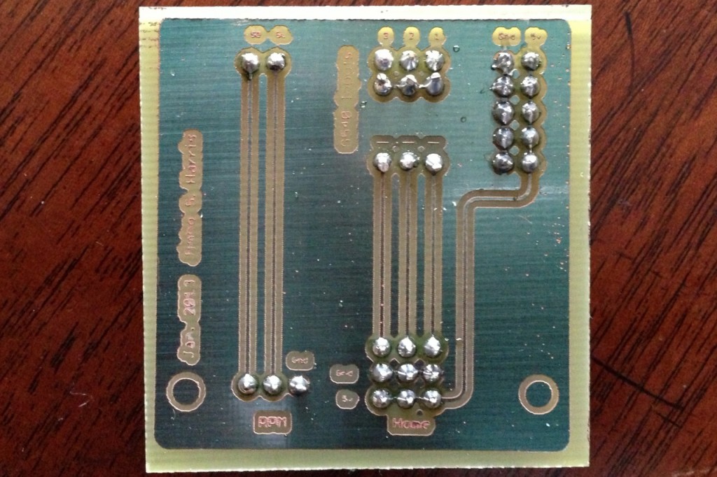
This is a daughterboard for the Super-PID on my CNC machine. It breaks out the power and RPM sensor for the Super-PID, and also exposes the inputs from the LPT port breakout box so that I can attach home switches to the X, Y, and Z axes.
I had already built this circuit in perfboard, but the home switches weren’t working properly, and I realized that I needed to add diodes on the parallel-wired Hall Effect sensors. I breadboarded a test sensor, confirmed that the diode made it work, and went about capturing the schematic in Eagle.
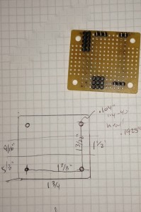
The original was done on perfboard. Note this one lacks diodes.
I had to match the original circuit form factor, because of the way it’s installed; half of the circuit lies inside the Super-PID case, and half outside. So I measured the distance between the mounting holes carefully.
I also decided to add a ground plane; etching away tiny little traces makes the etching go a lot faster.
I used a Sharpie to mask off all the parts of the board that didn’t have circuit on them. These two steps made the difference between “made it!” and “whoops, gotta head to the store again” today, because I realized as I was setting up that I am now officially out of vinegar. I had just enough to do one batch of etchant, so I had to make it work.
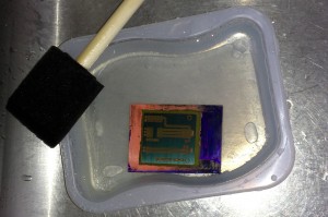
I used Sharpie to mask off as much as I could that wasn’t part of the circuit.
I love how clean the board looks with the ground plane.
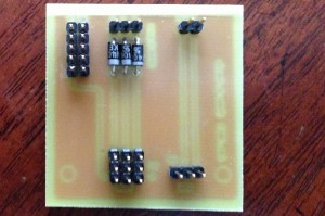
Looks pretty sweet from the top side.
I decided to leave the etch resist on, as I read somewhere that etch resist is actually intended for use as solder flux. I wonder if it will protect the traces long-term, too. The little green pads did hold solder pretty well.
Because I wasn’t pushing the etchant so hard, I got a lot of fine detail in this build; next time I might make the font a little darker, but even the really little stuff is readable.
In all, this board went together a lot easier than the last one, and I’m really pleased with the results. All the traces look really clean, and I didn’t have to do any editing with the tip of a utility knife this time.
So the actual workflow was about the same; I added in a ground plane, I cut the board to the size of the circuit, and I did some careful masking (note to self: next time, mask with tape instead of Sharpie). I made myself new developer, and it worked just fine this time (I used warm water). So I now have a jar of usable developer for next time.
I attempted to switch to HCl / Cupric Chloride etching, but the “30% Hydrochloric Acid” junk I got at the pool supply store was useless as an etchant — it was dyed orange, and spent a lot of time foaming and attacking the etch resist instead of the copper. Yuck. I’ll have to try HCl again sometime, but I have to find a brand that works. Maybe a hardware store instead of a pool supply place.
I also picked up some real cheap “Injectorall” boards from Digikey. I was Not Impressed. The boards did not come with a peel-away protector for the photoresist, just a black plastic bag with a white piece of paper over the resist. Also, the stuff apparently really does want UV light, because 20min under a 100W lamp did not make much of an impression. It also took forever to develop, and when it did, there were huge holes in the resist where I could see pink copper underneath. In short, those boards are destined for being stripped of resist, and used for toner transfer or art projects.
In contrast, I used an MG Chemicals board last time, and a Datak board this time, and they both worked fine. Nice green resist, took the artwork well, etched up fine even with the weak vinegar/H2O2 solution.
I need to figure out transparency film. There are apparently 5 or 6 types with varying price points. But the guy at Kinko’s really hasn’t gotten a nice, dark print for me yet, even when I requested he make it as dark as possible today. So I think that I’m going to have to figure out how to produce dark lines on transparency on my own. I mean, the artwork is coming out “OK” on the boards, but it seems like it should be.. darker. Much, much darker.
I finally installed a light on my drill press, so I can see what I’m doing with the little teeny through holes. I drilled the whole board without breaking a drill bit. w00t!
It was very satisfying to see the limit switch light up on the PC when the Hall Effect sensor tripped.