It’s impossible to describe what the kitchen smells like right now.
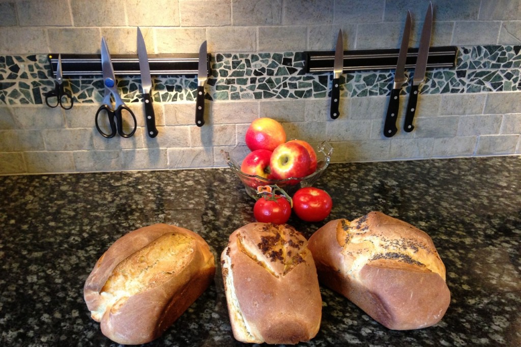
This represents 3/4 of my second attempt at baking bread from scratch. Sorry, one loaf had to be sacrificed to the wolv– I mean, family — before I could get enough peace and quiet to get a photo taken. 🙂
I’m happy to report that this bread run was just as successful as my first.
I used the same Betty Crocker recipe that was taught to me by my Bread Jedi instructor, a Sage of the Woods who shall otherwise remain nameless. (Thank you, N__!)
The recipe is pretty simple, but it still takes enough work that it’s worth doubling to get 4 loaves instead of 2.
With supreme confidence, I totally skipped blooming the yeast, in favor of just mixing the whole thing together at once. It seems not to have caused any problem whatsoever.
I picked up 4 bread pans at the local grocery store, along with a couple of large Tupperware tubs (I mixed in these, and there’s also another batch of dough in the fridge, waiting for me to bake it over the next week or so).
This was a standard double-rise, hand-kneaded dough. I really enjoy kneading. Everyone complains about it, but I find it a great stress reliever. It’s also really easy to tell when the dough is done, because you literally have your hands all over it. Having said that, my daughter helped out with the measuring and mixing part, but strangely disappeared as soon as it came time to knead.. hmm…
Here’s a quick look at the loaves after the first rise and punch down (I love that you actually have to effect violence on the dough… this is not like roasting). See? Four loaves. Honest. I wasn’t sure when to add the poppy seeds… this was not the correct time. Oops. No harm done.
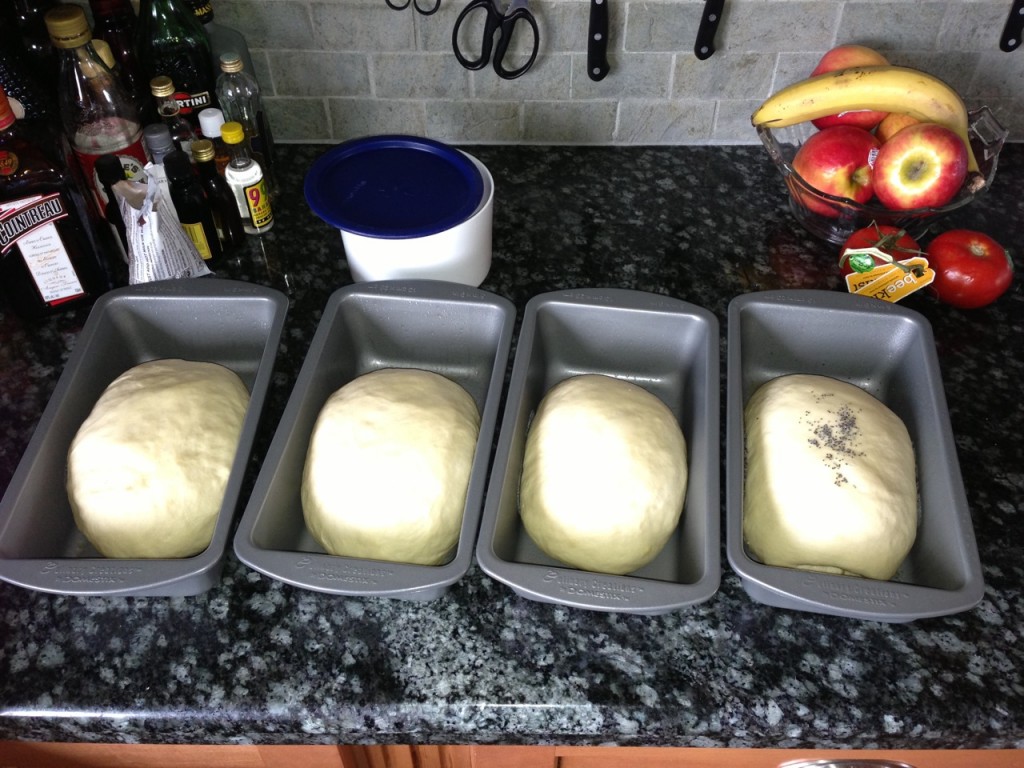
Those who are about to rise, we salute you.
I slashed the tops this time (hadn’t done that the first time around), and also experimented with some toppings; poppyseed, anise seed, rosemary, and granola. I like the way the V slash came out the best (poppy), but I have high hopes for the scallop slash (granola). Also, I need to brush on water, butter, or egg, to make the toppings stick, I think. Shrug. That’s for next time.
The oven had been pre-heating for awhile, because I’d picked up a 12″x12″ piece of granite at Home Depot to eventually use as a baking stone, and I was making sure it could deal with temperature changes. The baking was done in about 30 minutes (recipe calls for 35). The tops are looking pretty “GB & D”, the bottoms are perhaps a little overdone (but the bottom crust is still very tasty). The crumb is… well, the bread is awesome, if I do say so myself. Loaf #1 was gone in about 15 minutes flat.
I picked up a breadmaking book (no plug until I taste your recipe!), and I’m going to try Brioche next — I like egg bread a lot, and we’re up to about 45 eggs at the moment, so I need to dig into our backlog.
Thank you again to my teacher and master breadmaker, N___. Couldn’t have done it without you!