
I knew that I was getting pretty close to being done with the Super-PID installation.
I had a bunch of cable connections to make, and the board was pretty much ready to install into its new case.
I decided to deal with the 3 exposed G540 ports (input 1 for home switches, inputs 2 and 3 currently unused but broken out in the DB-9) first. I crimped on some servo pins, added a (female) servo connector, messed around with it until everything fit, and that was that.
Next, I put together a servo connector for the power and ground wires. These are coming directly from the PC power supply, and will be supplying power to all the 5v circuitry in the Super-PID, as well as the home switches (and eventually whatever else I add to the other inputs). One pin was empty, of course, but servo connectors are so easy to use that I like the idea of standardizing on them where possible.
Then I made 3 cables that terminated in bare wire at one end (for 2 different power connections on the Super-PID, and for the SL and SO on the RPM sensor) and servo connectors on the other.
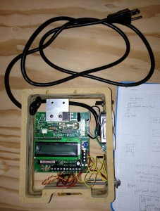
With all the cable terminations done, I was ready to start hooking everything up. I attached the 110v stuff carefully, hooking the mains input to the Super-PID and the mains ground to the ground on the outlet. Then I hooked the Super-PID 110v output to the AC outlet. I taped the outlet’s side studs, as they will not be completely inaccessible the way the case is set up.
Then I hooked the DB-9 power, 2 power sources on the S-PID, G540 inputs cable, RUN, TACH, and POT wires from the DB-9 and the RPM sensor connection (inside the case). Things look a little bit messy, but the cables are all hooked up, and the Super-PID is almost ready to test!
Next steps:
– put a servo connector on the RPM sensor cable
– make a “back” for the S-PID case (for the Super-PID and the perfboard to bolt to)
– make a “front” for the S-PID case (either clear or with a hole for the LCD
– Bolt the whole thing to the CNC machine.
And suddenly I will have router speed control!
I may decide to hook up the potentiometer and a SPDT switch to allow me to switch from computer control to manual control of the speed. I can make that decision when I build the front of the case.
I could potentially also hook switches to the “RUN” pin for:
– being able to turn off the router manually
– driving a 5v/120vac relay to turn the vacuum on and off
but that’s for another day.
Today, I’m happy that I’m very, very close to finally getting the S-PID installed. It’s been sitting around for over a year now.