

Mellow greetings from my new robot friend.
The “spare” Z axis motor arrived today. A bit of solder and I was ready to test it out.
It took a little bit of time to get the hang of the basis vectors for the machine (where is (0,0,0), and which directions are up, forward, and away?). Once I got that nailed, though, my first test cut, a square, came off without a hitch.
Buoyed by this success, I spent the next couple of hours learning how to cut text. Turns out it’s pretty simple. All the fonts are available, and the toughest part is figuring out the “machining” part of the equation; my first cut was in millimeters, I decided that I wanted to cut with the text rotated 90deg to make best use of my workpiece space, etc.
I also learned that working with really tiny pieces of wood is not as easy as you would think. Clamping in particular is a bit tough. So my first “real” cuts were done in large pieces that I could clamp from the edges of the table, making it important for me to know exactly how much room the Y-gantry had to move around in (or else I’d hit a clamp…).
I settled on 2″ high letters, and the text ended up being about 12″ long. The reason that it’s a shorter version of the classic “Hello, World.” is because all that extra text would have meant more tweaking of the font size to get it to fit on the cuttable area, and it was getting late. So there you go.
Here’s a photo of Mach3, the “control” software, running the G-code for the text.
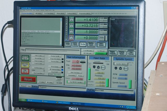
The G-code was created by the “CAM” software. Normally, I would have had to use all 3 pieces of the software toolchain to get a cut sent to the machine, but Text is such a basic function that in fact, Mach3 itself has a plugin for it, but I couldn’t get it working, so I decided to check whether the CAM software could do it, and it could, so I did it that way.
CamBam is decently powerful. I had to figure out a few pieces of jargon in order to get it to work. I quickly figured out that trying to “trick” it (by putting in a workpiece thickness of 0, for instance) was just making life tougher. So I put in the actual tool width, work thickness, and desired depth, and things went more smoothly from there.
To test out the cuts, I set the “Z zero” point in Mach3 to about 2″ above the table, then ran the G-code. I made sure that it looked like things were moving in the right direction, and tweaked the CamBam settings as appropriate to make things look right before actually cutting the piece.
A side note: when “engraving”, CamBam added an extra G0 Z1.0, which sent the router 1″ *into* the piece, right before doing the rest of the cuts. I assume that was supposed to be a G0 Z0 to “home” the Z axis, but I couldn’t figure out how to make the CAM software do that properly, so I ended up editing the G-code myself. No biggie.
It took about 5 minutes or so to cut the letters out. I am limited to about 1/8″ depth of cut right now because of the router bit that I am using. When I switch to a longer bit, I will be able to cut out pieces, rather than just engrave in the surface.
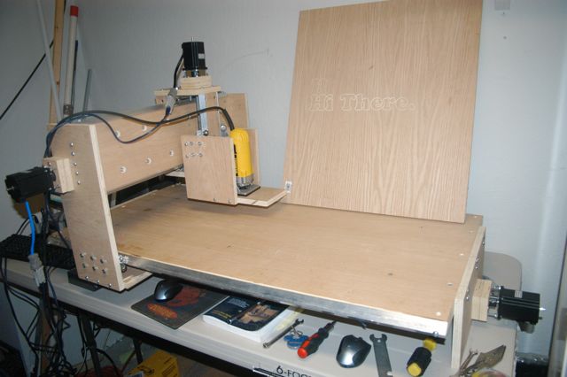
For everyone who has been following along (and for the people who find this blog later and wonder where the “build” photos are), here, at long last, is a photo of the yet-to-be-named CNC machine:
…and just in case you are into the electronics parts too, here’s a shot of the computer and motor driving gear:
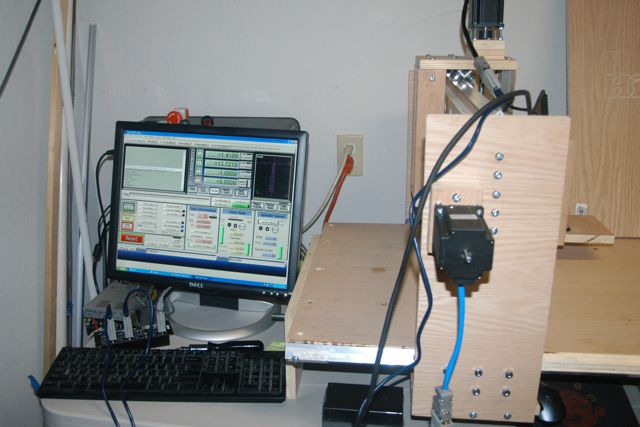
The computer is an old desktop I had lying around (doesn’t take much to run Mach3), you can see the mouse and mousepad under the machine.
The silver box is the 48vDC/7.3A power supply. I have not yet hooked up the E-stop or power switches (you can see them sitting on top of the PC).
The black box with the DB9 connectors is the Gecko G540. It serves as the translator between the step/direction commands from the PC (via the parallel port) and the coil energization sequence of the motors. You can see that there is nothing hooked up to the “Y” controller, and that the Y axis is hooked up to the “A” controller, if you look closely.
I need to build a case for the electronics. In particular, I would like there to be a power switch for the DC power supply. I have been thinking that it would be cool to put the stuff inside the PC case if I can; it has a built-in fan, and seems like there should be enough room. I’ll look into it.
All in all, I’m pretty satisfied with how well things have gone so far. I’m making sawdust!
Seems like I shouldn’t call these posts “CNC ‘Build'” anymore…
It is beautiful
I love it – I want one –
Allright! Two points.
Congrats it looks pretty good for ready rod.
ACME screw or Ball bearing screw is in the upgrade path. But the first upgrades will include basics: adding a power switch, Emergency Stop switch, home and limit switches, and probably rebuilding the Z axis to allow the router to get to the material without losing 3/4″ off of all the bits because of the router mount.
Geeks of the world unite!
Can it cut/scribe glass? If yes, what would be the motion limitations?
In theory it could cut anything you can fit under the router bit. I would assume “soft” materials like wood, plastic, glass, carbon fiber, etc. would be no problem. I would probably not want to mill a block of metal (between coolant, rigidity, and tolerances, it would be a tough sell), but sheet metal is probably OK, too.
The cuttable area is about 20″x40″, maybe slightly more (22″?) in Y, since I narrowed the Z axis by about 2″ during the build. The Z travel is about 5″.
I have the rig configured in software for 30 inches per minute while cutting, but I could probably get it to go faster, maybe 100 ipm.
The machine could be upgraded to handle faster movement, a larger table, or different types of cutting tool. However, for some of those upgrades, the difference between “upgrade” and “redesign” becomes mostly semantic.
As it sits, my intention is to use it for plywood and solid lumber, printed circuit boards, aluminum sheet, and ABS plastic (or Delrin or PVC or…).
I don’t have any data on resolution vs. accuracy at this time; I can see cutting errors in the few test cuts I’ve made, but it’s not yet clear that those would pose any problem in achieving a 1/32″ level of accuracy, at least in wood.
I’m using 200 steps/rev motors driving 13TPI screws, with a motor controller that provides 1/10 microsteps, so it’s 26000 steps per inch resolution. In theory, there is plenty of resolution to achieve 1/1000″ tolerances (like one would want for metalwork), but I haven’t done enough cutting yet to see what’s really achievable.