
My last build of the RFID kit was a little messy, so I decided to re-wire it from scratch on a clean breadboard.
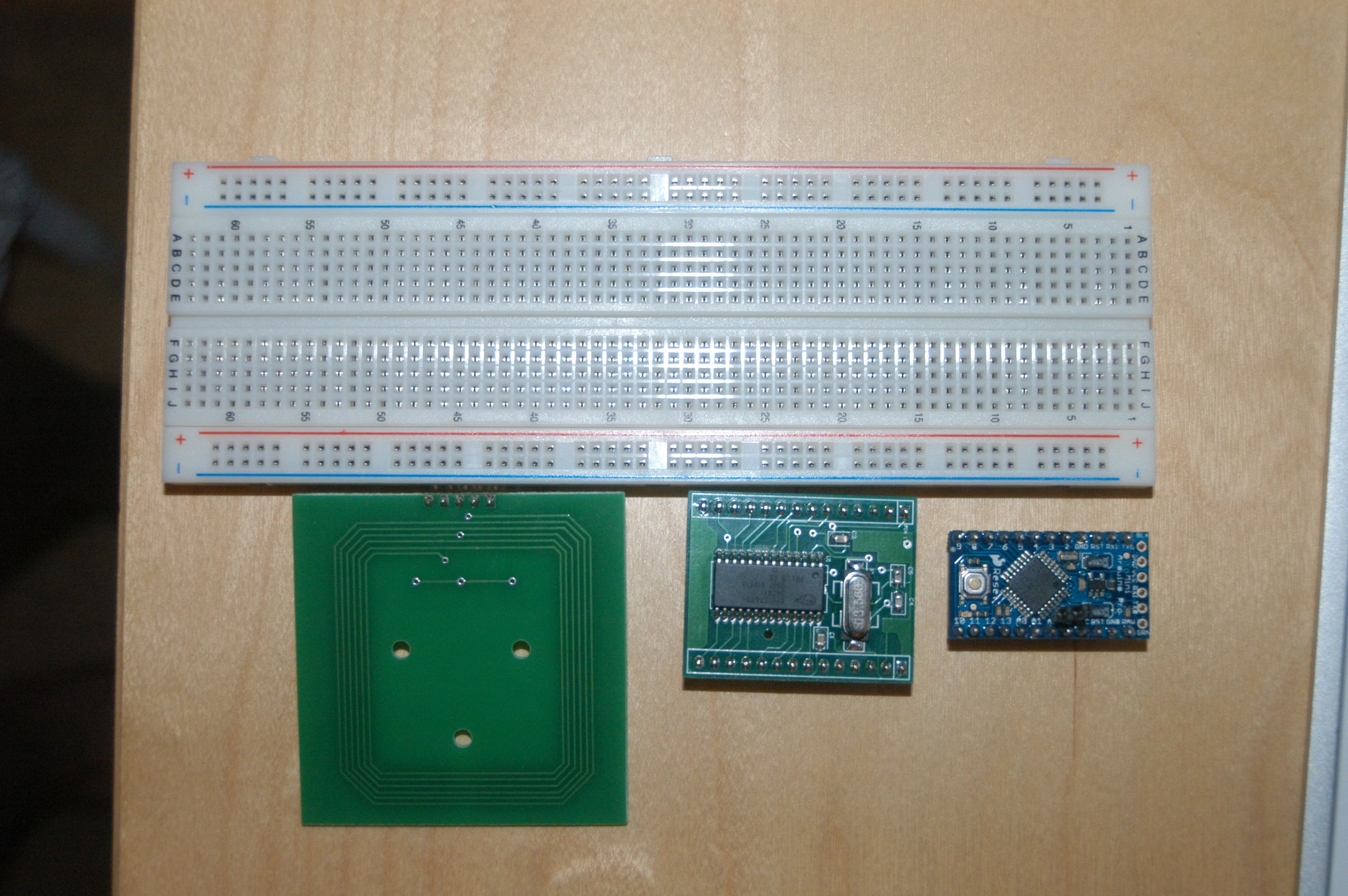
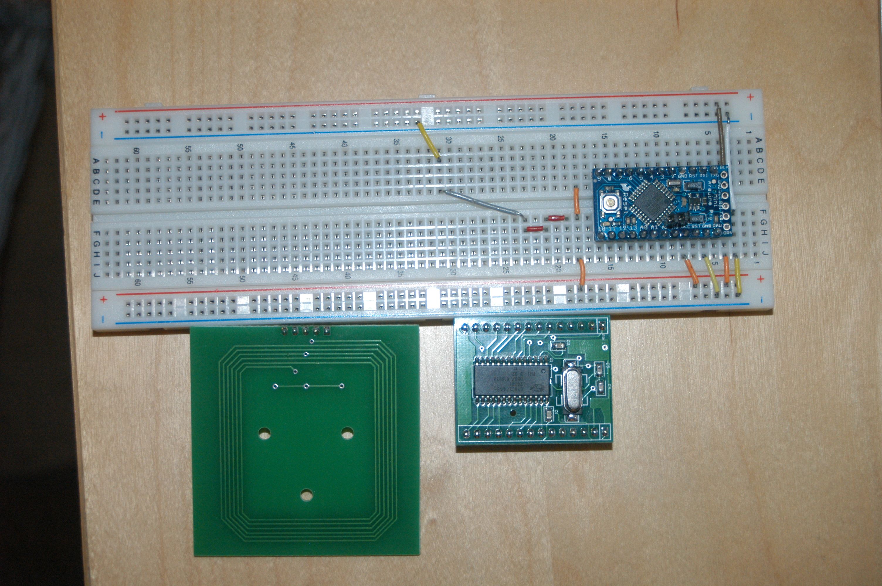
Here’s a photo of the empty breadboard with parts sitting next to it.
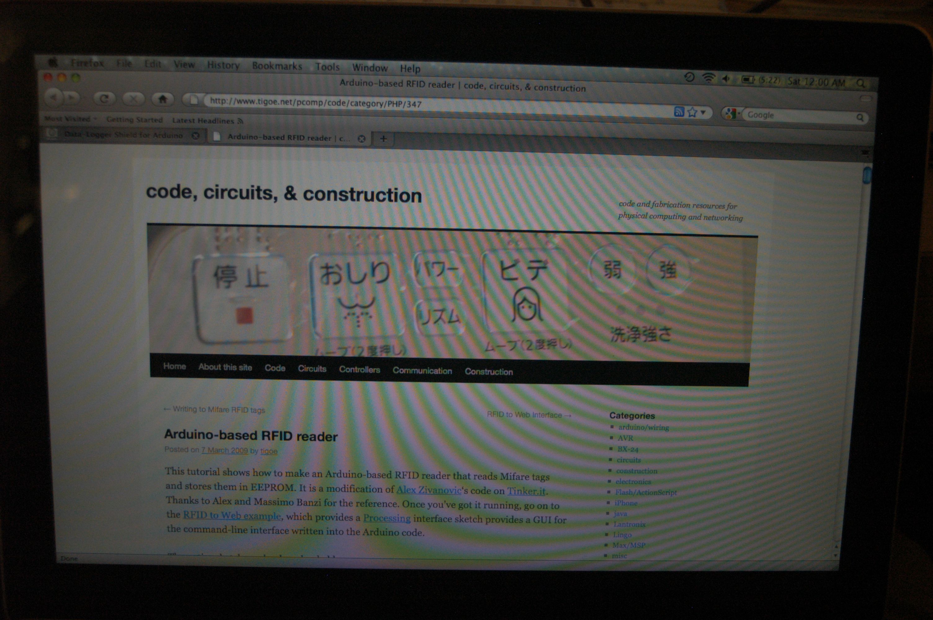
Here’s the website I followed. I gt the URL from the package the kit came in.
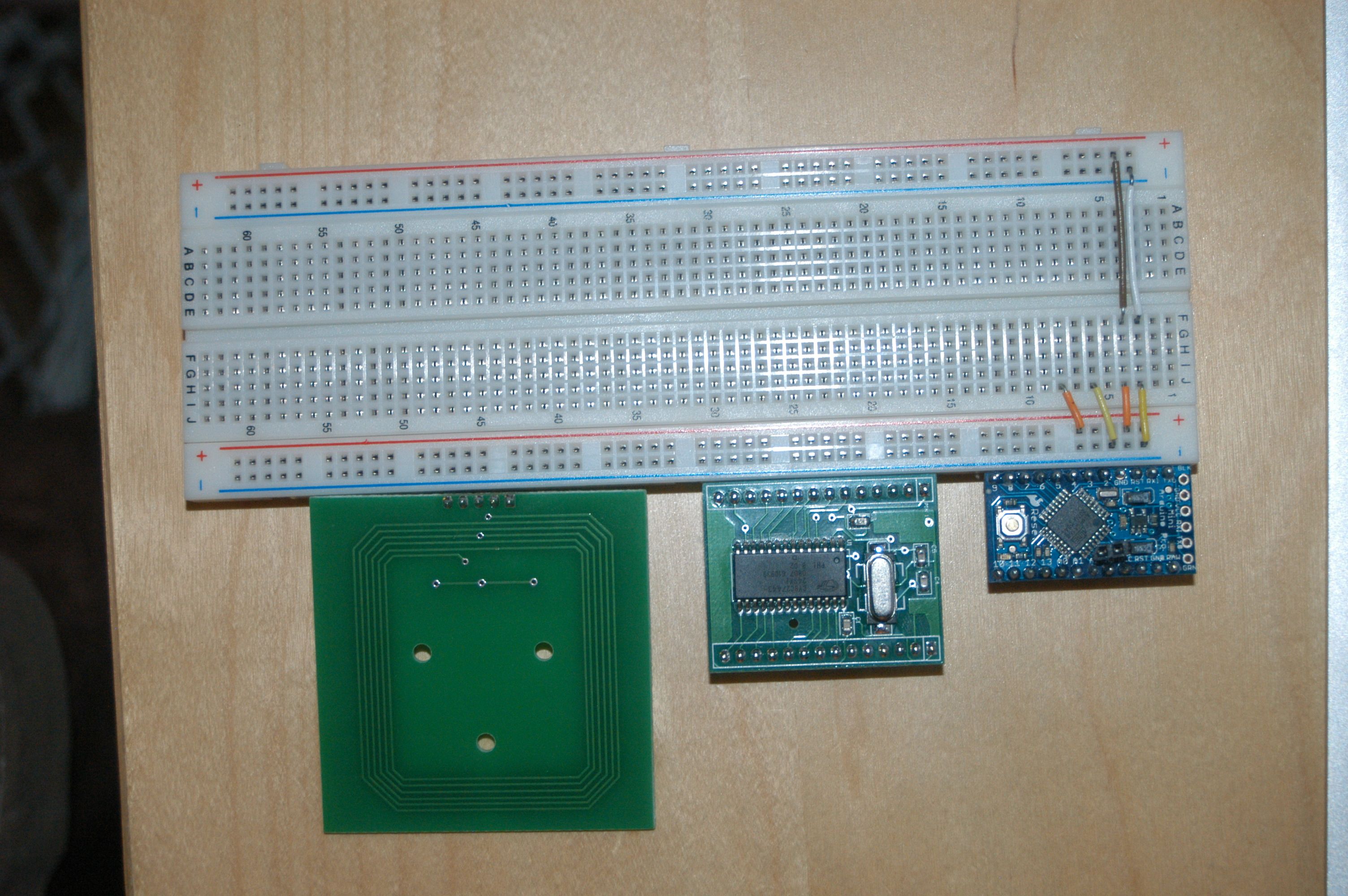
Here are the power and ground rail connections for the breadboard, and the power and ground for the Arduino.
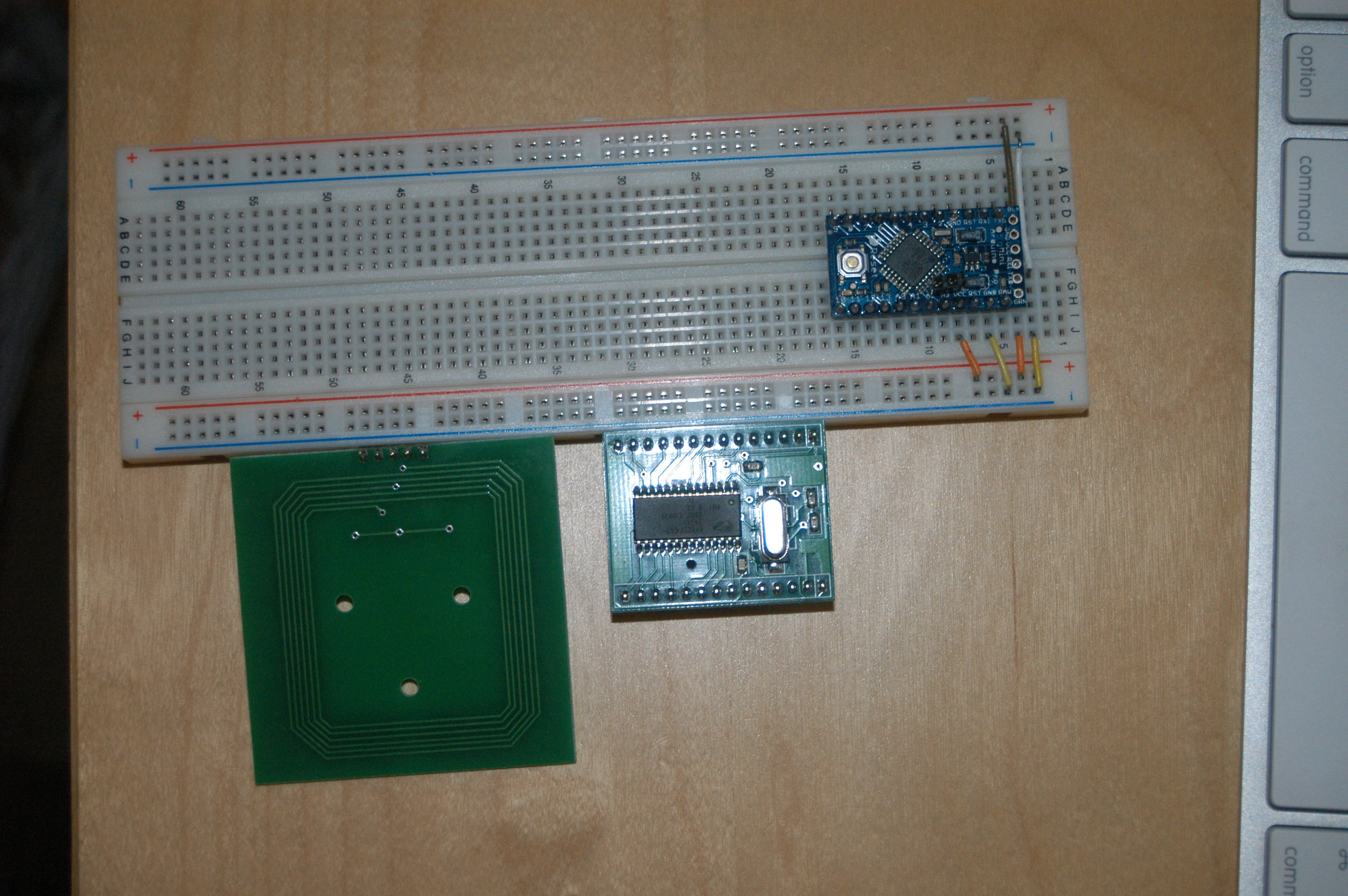
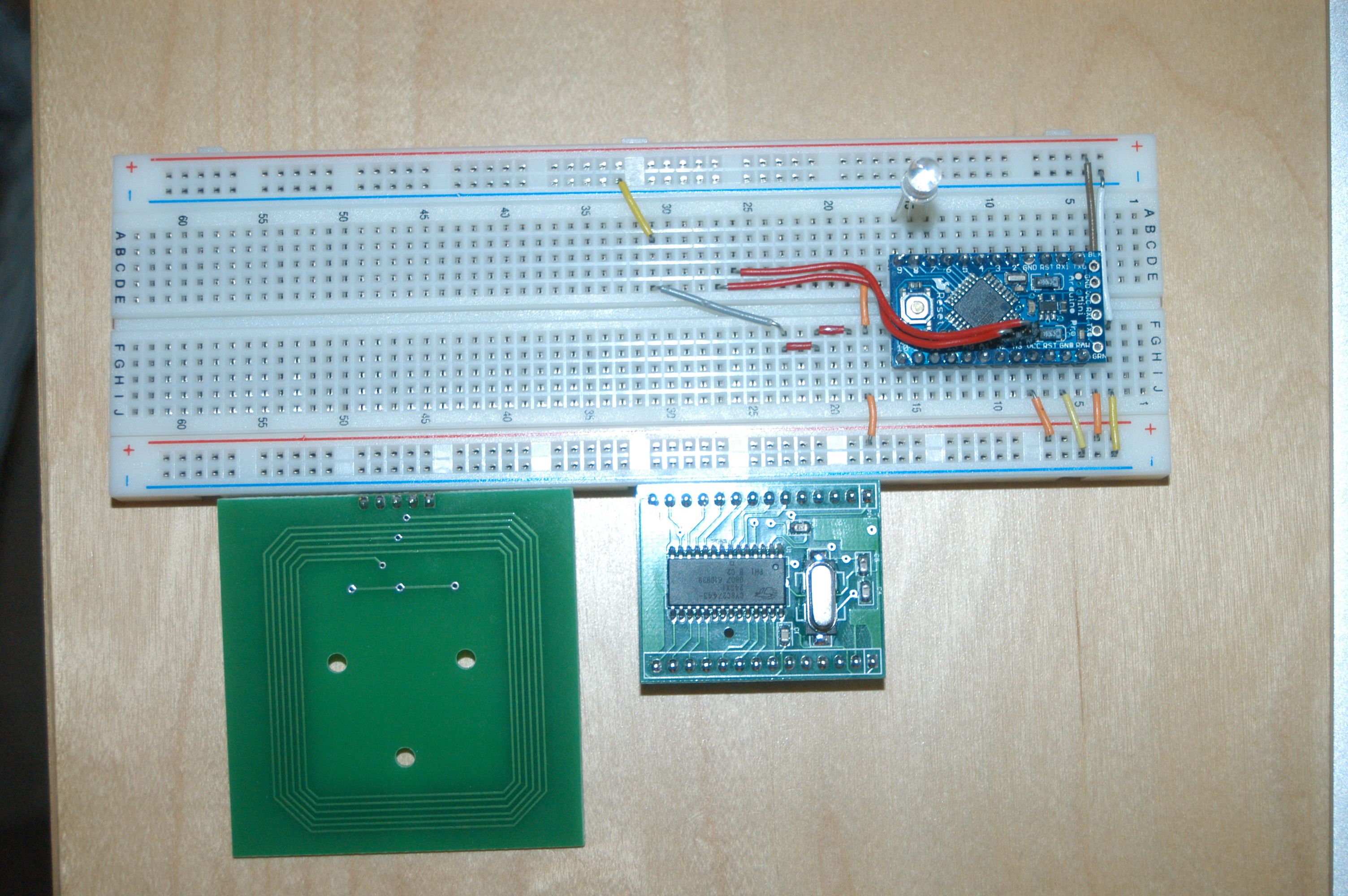
Here’s the Arduino installed.
Here’s the power and ground connections for the SM130.
Here’s the I2C data connections for the SM130. I also installed the RGB LED at this point. Note that I have the LED plugged into the ground rail, as it shows in the build diagram. <--- discrepancy
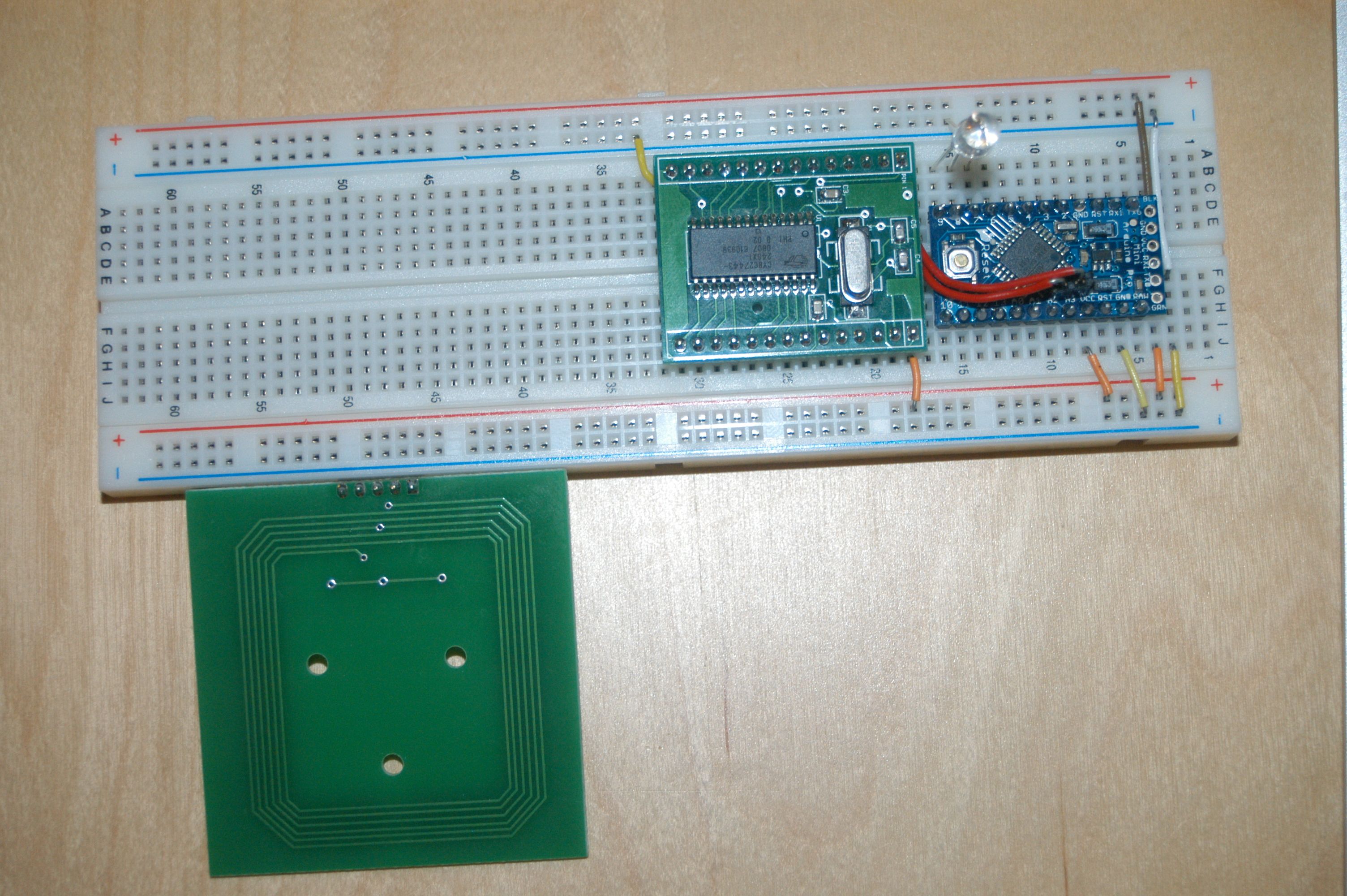
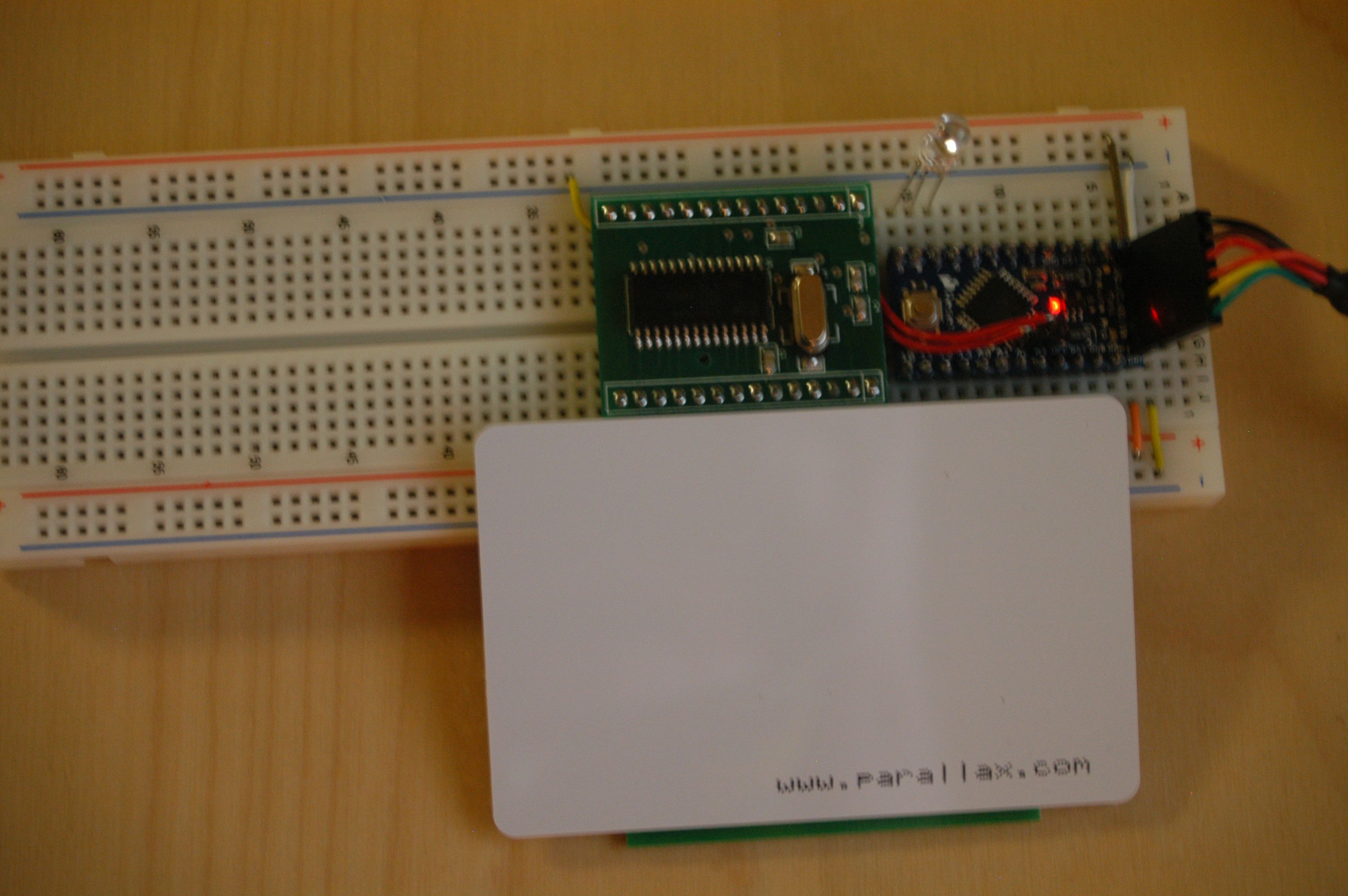
Here’s the SM130 installed.
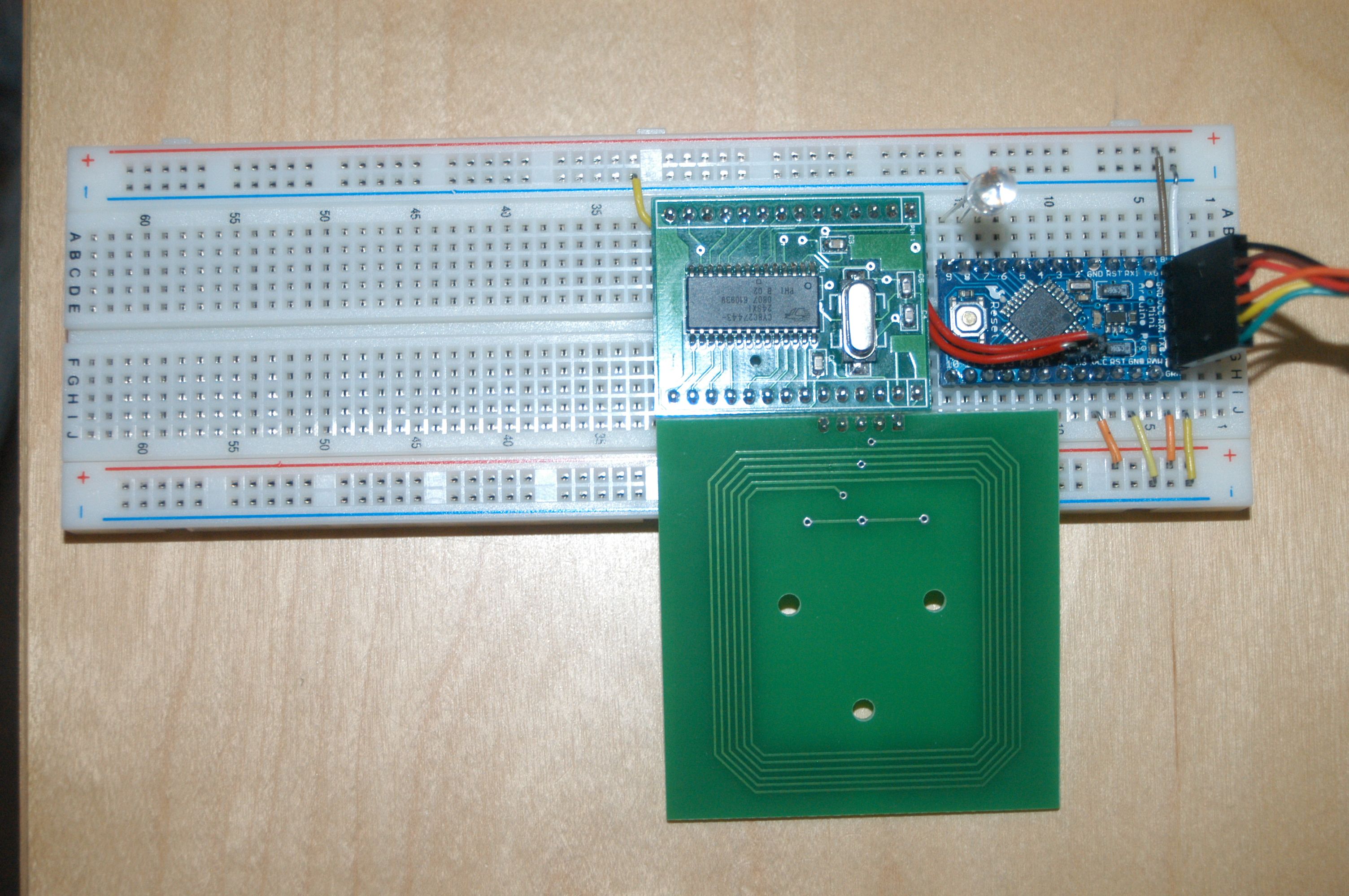
Here’s the antenna installed.
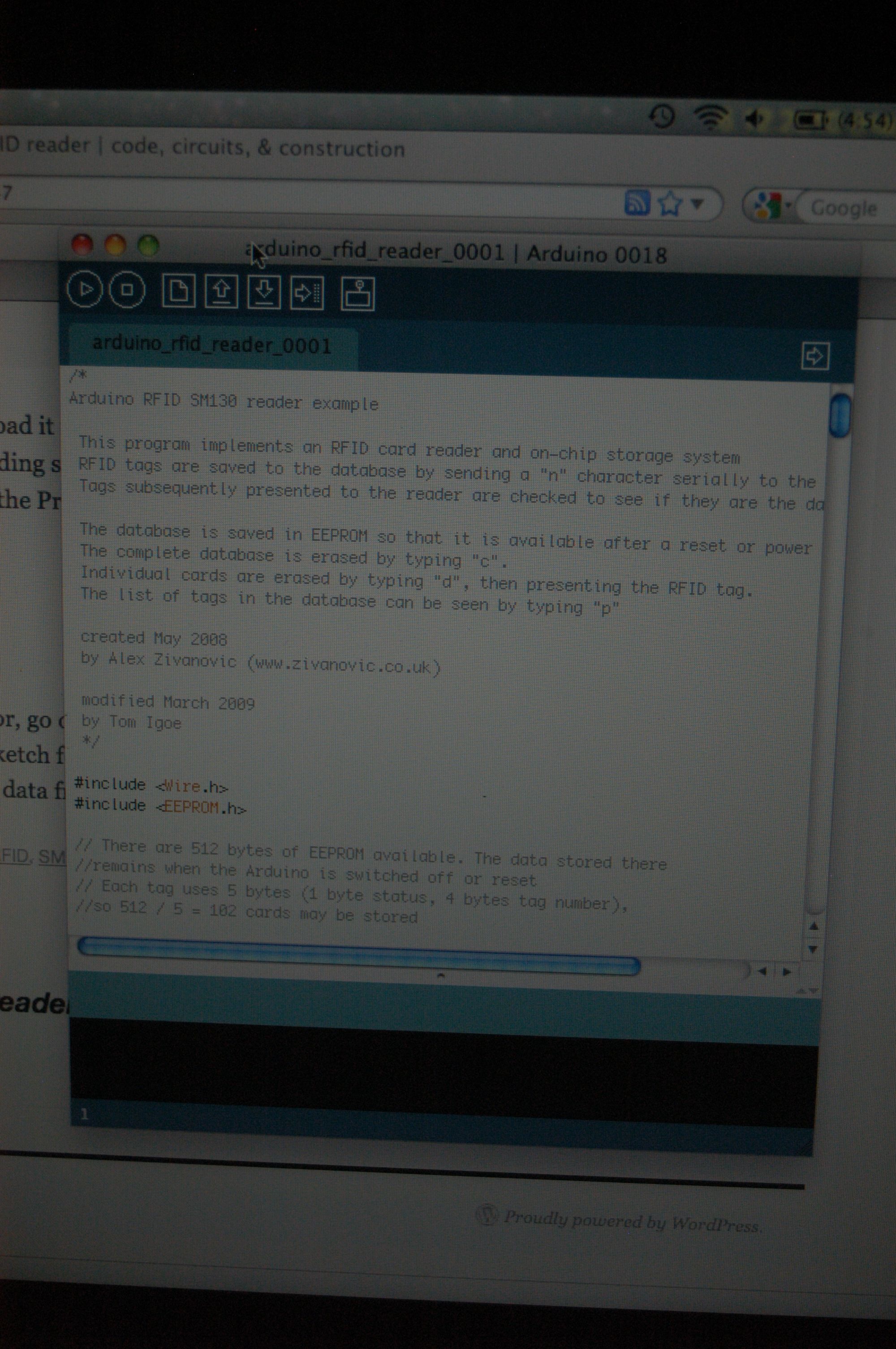
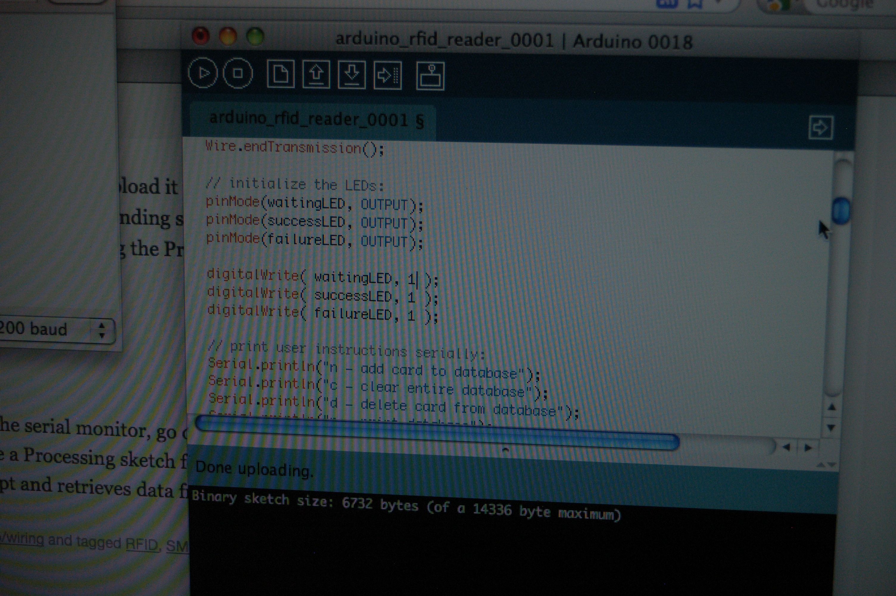
Here’s the freshly-downloaded sketch from the author’s website, loaded into Arduino-0018 on my Mac running Snow Leopard.
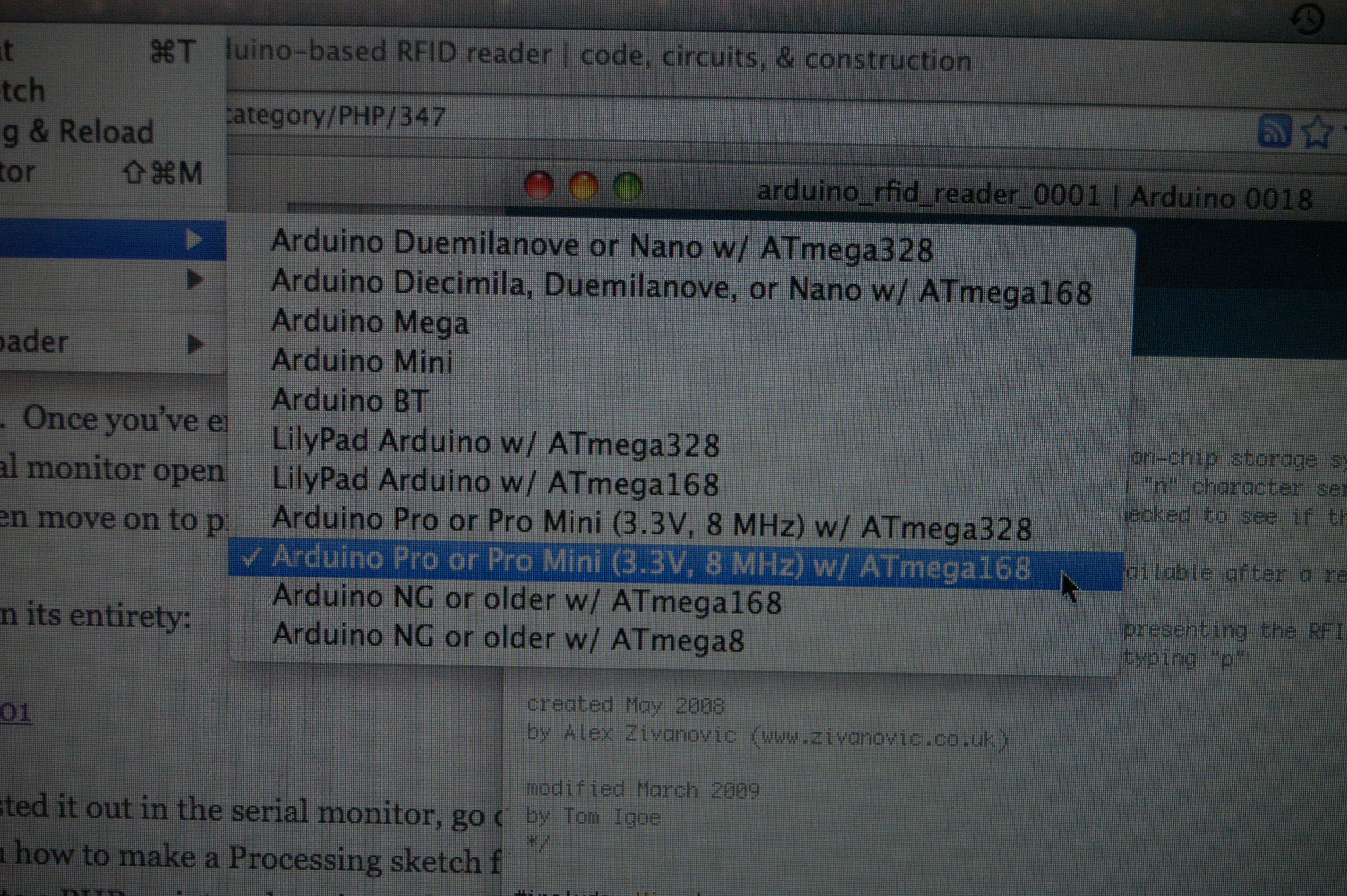
Here’s the board type I picked from the list in Arduino-0018. <--- discrepancy
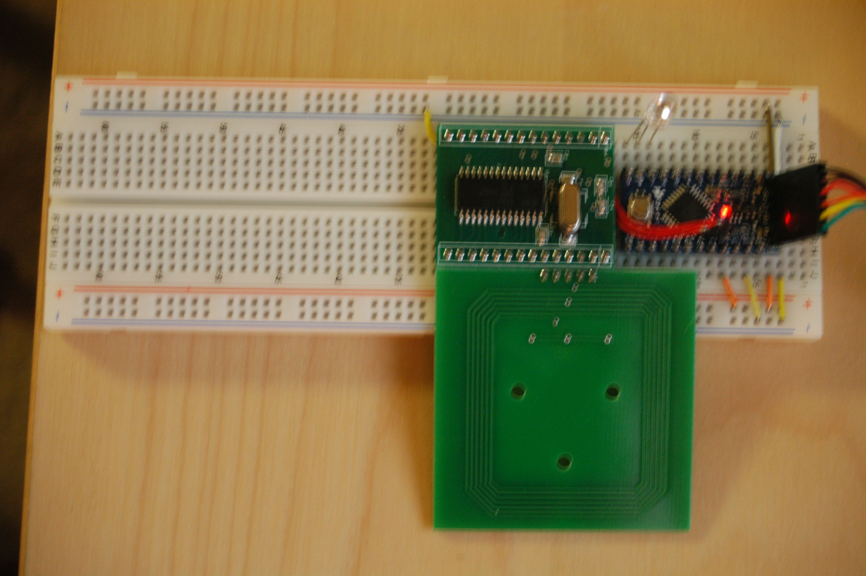
Here’s the circuit running the sketch. Note the red power LED is on, but the RGB LED is not blinking at this point.
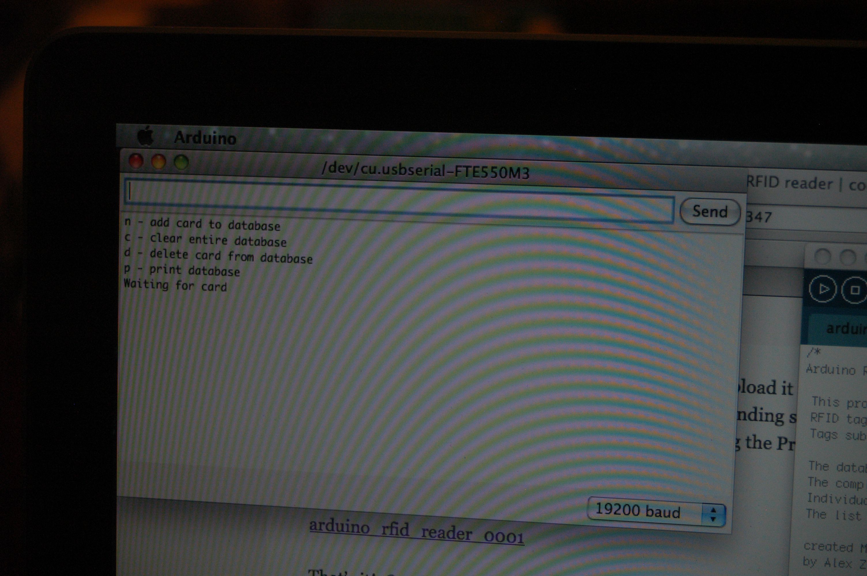
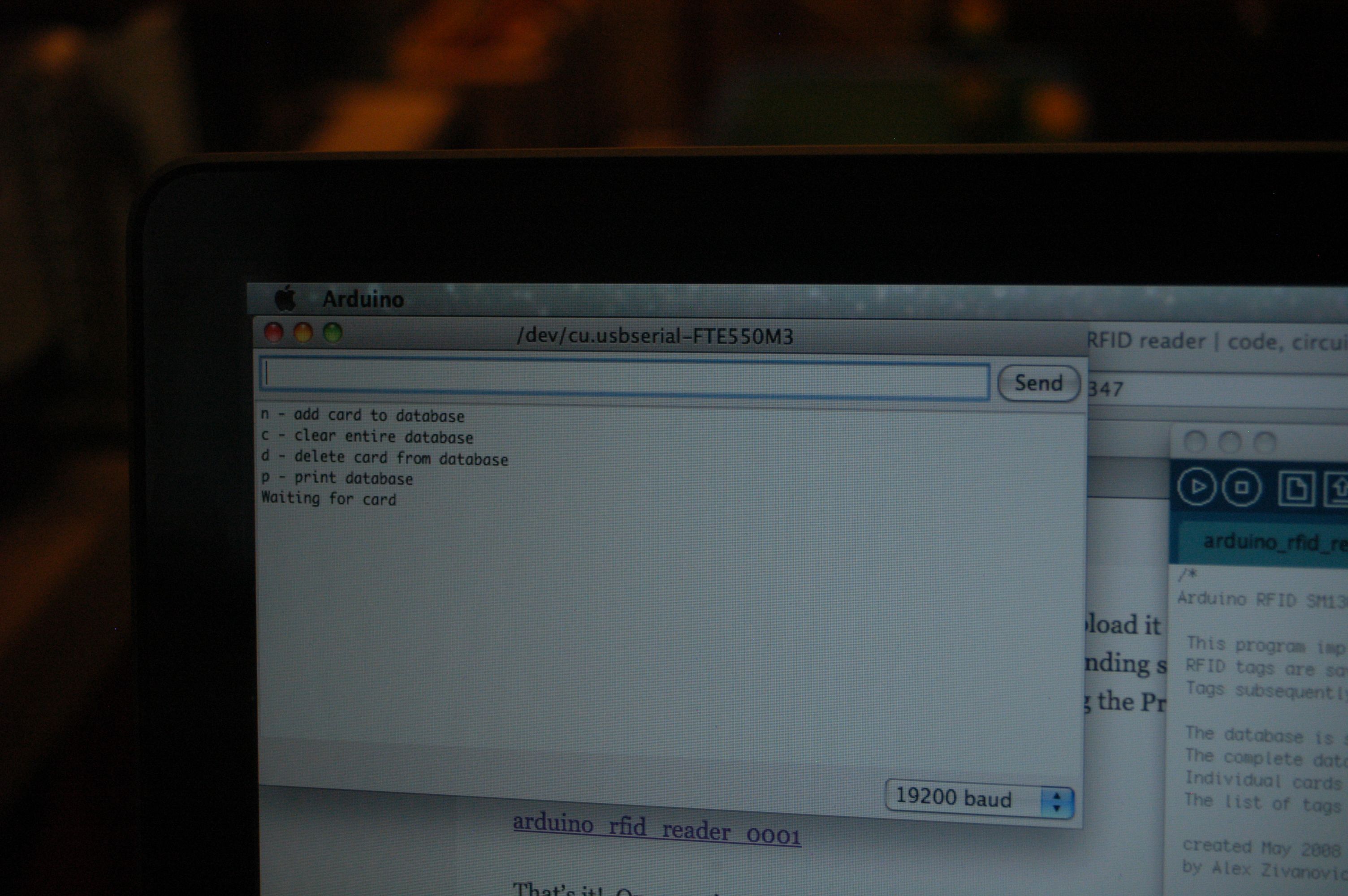
Here’s a photo of the Serial Monitor at this point (note that it’s in 19200 baud mode). <--- discrepancy
Here’s the circuit with the included RFID card sitting on top of the antenna.
Here’s a photo of the Serial Monitor at this point (note: no change since last time).
I noted that the LED was not lit, but the code was calling a “toggle” on the “waitingLED” (I determined this by putting in Serial.printlns in the toggle() function). After playing around a bit, I determined that the RGB LED is common anode, not common cathode. So I hooked the common pin to the positive rail instead of the ground rail, which resulted in all 3 colors being lit at once, with blue blinking on and off. So, I had to make a small code change to turn off the R and G parts of the LED:
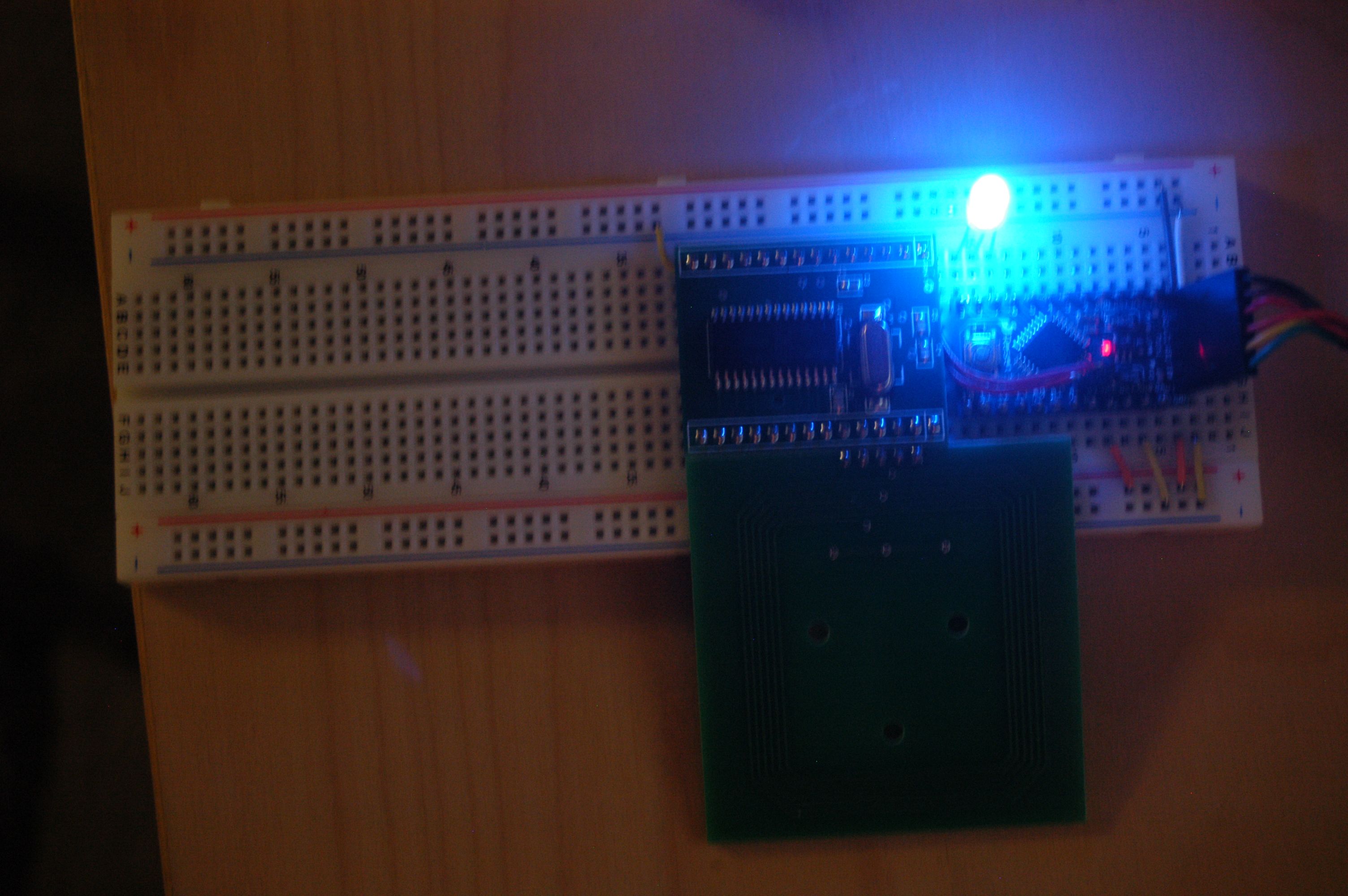
And now I get a nice blinking blue LED while it’s idling.
I noted 3 discrepancies between the way the circuit behaves relative to the way the code or hardware reads. I have noted them above.
1) The RGB LED on the author’s webpage is clearly shown to be common-to-ground, but the part that’s in my kit is common-to-positive. This required a code change to reflect the different circuit layout.
2) The Arduino included in the kit is marked “Mini Arduino Pro”, and has a CPU marked “ATMEGA168 20AU”, the 20MHz version of the ‘168. However, Arduino-0018 only shows 8MHz versions of the chip. It seems like I should be picking a different board. But which one?
3) Although the sketch opens a 9600 baud serial port (with “Serial.begin(9600)”), if I open a 9600 baud serial port, I get garbage, but 19200 displays the menu properly. This seems bad. Also might be related to the wrong board being chosen in the IDE.
In any case, the circuit still doesn’t work. The card is not recognized, and it’s not clear whether it’s the card, the antenna, or … something else… that’s gone awry.
Hi jimbo,
I dust this off again to give another try.
After searching this project again and after a couple of years. You are the only one with any real info about this RFID Reader Kit I could find.
Did you ever have success?
I cannot find anything useful on Tom Igoe’s website, anyone you know have a schematic and/or sketch (program). Thank you in advance!!
Barry
Hi Barry,
Indeed, I did, although it took me over a year to get back to it: http://www.jimbo.net/circuitfarm/2011/12/rfid-and-other-proximity-sensing/
Essentially, the RFID card that was included with my kit was of the incorrect type. The SM130 reads Mifare style RFID, which is 13.56MHz. The Parallax card (only ID on it is the URL http://www.parallax.com — they still sell this tag, and they don’t sell any Mifare products) included with the kit is NFC (?) style, which reads at some 112 kHz or something like that. The antennae used to read the two is completely different, and the SM130 can’t read the other style.
I picked up a 5-pack of Mifare RFID cards from Adafruit, and wouldn’t you know the circuit booted right up and worked like a charm.
By the way, I tried several different RFID-enabled objects that I had lying around (various secure-office door cards, my US passport, various security-enabled videogame and DVD cases, etc), and none of them were Mifare compatible. Until I dug into it enough to understand what was really going on, it was easy to assume that either I’d hooked it up incorrectly, or I had fried the kit somehow.
I spoke with Tom Igoe a couple times about it, and posted to MakerShed’s forum, and tried exchanging emails with support@makershed.com, and nobody even tried to hint that perhaps the kit wouldn’t work as-sold. I note with interest that MakerShed no longer carries the kit, however.
Once I got the Mifare cards, the sketch and instructions from Igoe’s site worked just fine.
I hope this helps you to get your kit up and running! Please do let me know if you have more questions. RFID is some really cool stuff, and it’s frustrating that nobody else has really mentioned the two different tag formats.
Best,
Jimbo